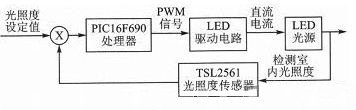
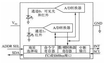
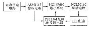
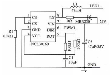
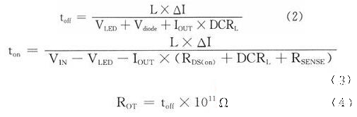
In this paper, LED constant-light dimming driver is designed for the problems of low energy efficiency and large power consumption of traditional lighting. The system uses the constant current LED control chip NCL30160 as the LED light source driving circuit, uses the TSL2561 illuminance sensor to collect the indoor illuminance, and performs closed-loop control through the corresponding algorithm of the processor to realize the indoor constant illumination dimming. The algorithm implements a smooth change of the PWM waveform to avoid flashing due to PWM mutation. At the same time, the system has increased the human body motion control to achieve different dimming schemes for no one and some people, so that the design is further energy-saving and intelligent. 1 System introduction and working principle The system consists of PIC16F690 microcontroller, TSL2561 illuminance sensor, LED light source and LED driver circuit. Since the brightness of the LED is proportional to the operating current, adjusting the operating current can adjust the brightness of the LED. At present, there are mainly two dimming methods for adjusting forward current and pulse modulation dimming. Since pulse width modulation dimming has the advantages of no color shift, high dimming precision, dimming in combination with digital technology, wide dimming range, no flicker, etc., pulse modulation dimming is used in this paper. The system mainly collects the illuminance feedback from the TSL2561 to the PIC16F690 processing chip, and performs corresponding algorithm processing through the PIC16F690 to output the PWM waveform which changes with the illumination law. The LED lamp is driven by the driving circuit with the PWM interface to realize dimming. The system block diagram is shown in Figure 1. Figure 1 Diagram of the LED driver system for constant illumination dimming At the same time, the human body motion control and button control are added in the system, which can detect the human body movement, automatically turn off the LED light when no one is used, further reduce the waste of electric energy; the button can adjust the frequency of the PWM waveform and set the maximum illumination of the environment, so that The system is more humane. 1.1 PIC16F690 microcontroller The PIC16F690 microcontroller features a high-performance RISC CPU, low power consumption, and a rich set of peripheral resources to meet the hardware resource requirements of the system. Because the MCU is rich in resources, it not only satisfies the system requirements, but also does not waste resources, thus reducing the controller cost. 1.2 TSL2561 illuminance sensor The TSL2561 is a high-speed, low-power, wide-range, programmable and flexible configuration light intensity digital conversion chip from TAOS. The chip's application provides the best display brightness and reduces power consumption. The TSL2561 has the following features: 1 Programmable configuration permission of the upper and lower thresholds of light intensity, when the detected illuminance exceeds the threshold, an interrupt signal can be generated; 2 digital output conforms to the standard SMBus and I2C bus protocols; 3 programmable control analog gain and digital output time; 4 ultra-small package and ultra low power consumption; 5 Automatically suppresses illumination fluctuations of 50 Hz/60 Hz. The internal structure of the TSL2561 is shown in Figure 2. There are two photodiode channels inside, channel 0 and channel 1, where channel 0 is sensitive to both visible and infrared light, and channel 1 is only sensitive to infrared light. The current flowing through the photodiode is converted to a digital quantity by an integral A/D converter, and the digital quantity is stored in a register inside the chip after the conversion. The integral A/D converter will automatically perform the integral conversion process after one integration cycle is completed. The TSL2561 can be controlled by setting its internal 16 registers, which can be accessed via standard SMBus or I2C bus protocols. Figure 2 Internal structure of the TSL2561 2 hardware design 2.1 Control circuit design The control circuit is mainly composed of the minimum system of PIC16F690, including reset circuit, input button circuit, download debugging circuit, power supply circuit, crystal oscillator circuit and corresponding signal input/output interface. Since the research of this system focuses on the dimming algorithm, and the system belongs to low power, the power supply circuit adopts a simple and practical RC circuit. The chip supply voltage is 3.3 V, using the ASM1117 regulator chip. Download and debug circuit According to the information provided by Microchip, the microchip integrated emulator ICD3 is used, and the interface circuit is designed according to the official data. The reset circuit and the crystal oscillator circuit are designed according to common circuits. The overall hardware block diagram is shown in Figure 3. Figure 3 overall hardware block diagram 2.2 drive circuit design 4 is an LED driving circuit based on a constant current LED control chip NCL30160. The NCL30160 is an NFET hysteretic step-down, constant current LED driver from ON Semiconductor. It boosts the current to 1.5 A and is a new generation of energy-efficient solutions with very low losses and small size to minimize space and cost. By utilizing a low on-resistance internal MOSFET of only 55 mΩ and the ability to operate at 100% duty cycle, a solution with up to 98% efficiency can be provided. The high switching frequency of up to 1.4 MHz allows designers to use smaller external components to minimize board size and minimize cost. Figure 4 drive circuit diagram Peripheral device parameters are calculated based on the NCL30160 data sheet and output requirements. The system uses five 1 W LEDs in series with a constant current of 350 mA. R1=200 mV/ILED=200 mV/350 mA≈0.56 Ω (1) In the formula, the ILED is the LED string current. The C5 in Figure 4 uses the values ​​recommended by the official data sheet. The inductances L1 and ROT are obtained by the equations (2) to (4). In the formula, the values ​​of toff, ton, △I, and RDS(oN) refer to the data sheet; VIN is taken here as 24 V, and DCRL is the inductor resistance, which is taken as 0 Ω. Elec Facial Bed,Electric Facial Bed,Professional Facial Bed,Electric Facial Bed For Sale TOM SPA BEAUTY SALON EQUIPMENT CO.,LTD , https://www.tomspabeauty.com