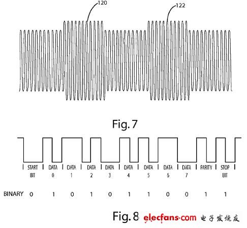
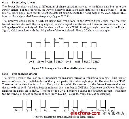
Earlier we explained the electromagnetic induction wireless charging core technology (1): resonance control , below we will continue to explore the data transmission part of the electromagnetic induction wireless charging core technology. The most important technical problem in the electromagnetic induction power system is that it is necessary to identify the object placed on the transmitting coil. The induction power will emit strong electromagnetic wave energy like the induction cooker. If this energy is directly applied to the metal. In order to solve this problem, each manufacturer develops a technology that can identify the target. After several years of development, it is confirmed that the receiving signal from the receiving end of the receiving end receives the signal from the receiving end of the receiving end as the best solution for the completion. The function of data transmission on the induction coil is the most important core technology in the system. It is very difficult to transmit data stably on the induction coil that transmits power. The main carrier is used for high-power power transmission, which is subject to various interference conditions in the use of power. In addition, it has previously been mentioned that this is a variable-frequency control. System, so the main carrier operating frequency will not be fixed. Because of the difficulties, the technology introduced by previous manufacturers has the power supply in addition to the induction coil, and the establishment of a wireless communication channel, such as infrared, Bluetooth, RFID tags, WiFi, etc., but with the cost principle that these modules have violated, this product is Chargers, the cost must be controlled to be quite low to be accepted by the market, so the use of the induction coil itself for data transmission is a must-have method in the industry. Using the coil of inductive power for data transmission will encounter two problems, namely, how to send data and how to receive data. The principle is the same as the data transmission method of RFID. The main carrier on the power supply coil is sent to the receiving end coil, and then The power circuit controls the load change for feedback. In the current inductive power design, it is a one-way transmission, that is, the power energy (LC oscillation main carrier) is sent from the power supply end to the power receiving end, and the power receiving end feeds back the data code to At the power supply end, the power received by the power receiving end is only strong or weak, and there is no communication component. The data transmission mechanism is only received when the power receiving end is close to receive power energy, and no power is supplied at the power supply end. In the situation, data transmission cannot be performed. It seems that only half of the communication mechanism is very practical in the inductive power system, because it satisfies the functions required by the system: the power supply end recognizes the power receiving end and then turns on the transmitting energy for power transmission. The power status returned by the power receiving end is adjusted by the power supply terminal. Refer to the figure (6) in the qi specification for receiving power and data feedback architecture in the power receiving end. It can be seen that there are two design architectures, namely resistive and capacitive. The method of resistively modulating the feedback signal is derived from passive RFID technology, which uses the receiving coil impedance switching feedback signal to the transmitting coil for reading, and is applied to the inductive power of the US Patent Publication No. 20110273138 WIRELESS, filed by ACCESS BUSINESS GROUP (Fulton), USA. CHARGING SYSTEM (Taiwan Publication No. 201018042 Wireless Charging System) mentions that the load resistance of the switch is located behind the rectifier of the receiving end, that is, Rcm in Figure (6) feeds back the impedance characteristic change on the coil to the power supply coil. The detection circuit is changed by the detection circuit on the power supply coil, and the software in the processor on the power supply side performs the decoding operation. Referring to Figure (7), in the patent specification, Fig. 7 shows the signal condition on the power supply coil. When the switch on Rcm is turned on, the impedance on the power receiving coil is pulled back to the power supply coil to increase its amplitude. In the coding mode, the asynchronous serial format is used in the UART communication mode, that is, whether the modulation state change occurs at the time point in a fixed timing period, and the logical data code is interpreted, but the coding mode can be sent. There will be a period of time that continues in the modulation state. Refer to Figure (8) for the data transmission format in the qi specification. It can be seen that the data transmission frequency is modulated and decoded by a 2KHz timing frequency. It is estimated that there will be a period of up to one in a state of adjustment. The time is in the modulation state. The length of the modulation state in the UART communication mode does not affect the function in the system, but the modulation state affects the state of the power supply in the inductive power system. The reason is that the main carrier of the power supply terminal is used to transmit power. The effect of the coupling between the terminal and the receiving end coil can transmit a strong current driving force, and the resistive load of the receiving end needs to bear the driving current for feedback. When the power is increased, the power on the Rcm is also increased, and during the modulation period. The current that is going to the output of the power receiving terminal will also be shunted by Rcm, so the output capability of the receiving end will be lost during modulation; in addition, the modulation time will be shortened due to the increase of the transmission frequency, because in the inductive power system The operating frequency of the carrier can only be operated at a lower frequency (about 100~200KHz) due to the limitation of components and electromagnetic interference regulations, and the data is transmitted by the modulation state on the primary carrier, so the data transmission frequency needs to be much lower than the main The carrier frequency can operate smoothly. Under the conflict of the foregoing conditions, it can be found that when the power of the inductive power system design is increased, the resistive load Data modulation scheme is not feasible, because the resistors in the modulation circuit will be relatively long period caused by the power consumption in the ON state. Figure (6) qi specification book receiving power and data feedback architecture Figure (7) US Patent Publication No. 20110273138 WIRELESS CHARGING SYSTEM Content Lightning Cable is one of our most important products , which is used to connect Apple mobile devices . It contains Short Lightning Cable , long lightning cable , Braided Lightning Cable , leather lightning cable , etc . Lightning Cable Lightning Cable,Short Lightning Cable, Braided Lightning Cable,Iphone Lightning Cable Hebei Baisiwei Import&Export Trade Co., LTD. , https://www.baisiweicable.com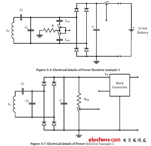
Lightning cable fit for iPhone iPad and iPod , With lightning connector to your computers USB port for syncing and charging Connects the USB power adapter for convenient charging from a wall outlet .
Color : black , white , red , gold , gray , blue , silver , pink .
Length : 1.5ft , 3ft , 6ft , 10ft , etc .
Type : 8 pins lightning to USB charger cable .
We focus on independent research and innovation, providing more durable , cheap , high quality , cool lightning cable to our customers . it hits all the right notes in terms of design, functionality, and price. It`s impossible for us to test every Lightning cable, but having tested hundreds of them since Apple replaced the 30-pin connector in 2012, and after comparing the PowerLine cable against our previous top picks, we can say that MaiMi cable stands out from the crowd.