Digital TV technology and its application
As we all know, digital signals have many advantages compared with analog signals. For example, in terms of noise, as long as the noise level is lower than a certain value, the digital signal can be processed to remove the noise; in terms of distortion, by selecting the sampling frequency and increasing the quantization Accuracy and improved bit error rate, distortion problems can also be solved. In addition, digital signals have many advantages in terms of signal generation, processing, and storage, and can encrypt signals by encoding and achieve signal bandwidth compression and the like.
This article refers to the address: http://
After the digitalization of the TV, the TV channel can be greatly increased. Today's cable TV can only offer less than 70 TV channels (6-8MHz/ch), while digital satellite TV can provide 200 programs. As people demand TV programs and other information, it is necessary to increase the number of channels. If digital compression technology is applied, it is now possible to transmit 4-10 sets of programs in a 6-8 MHz bandwidth, thereby transmitting 700 sets of programs. The digitization of the TV also facilitates the provision of interactive services such as telephony, data transmission, program on demand, home shopping, distance learning, and the like.
First, digital signals and analog signals
Signals can be divided into two major categories: analog signals and digital signals. The analog signal has a continuous infinite number of values ​​corresponding to the time axis, which completely and accurately represents the signal level, such as speech, image, etc., is an analog signal. A digital signal has only a limited number of values, discrete and approximately representing information, such as digital television, telegraph, etc., is a digital signal.
The system for transmitting analog TV signals is called an analog TV system. The system for transmitting digital TV signals is called a digital TV system. Digital TV is the future development direction.
In daily life, we use 10 numbers of 0, 1, 2, 3, 4, 5, 6, 7, 8, and 9 to form decimal calculations, while digital TV works based on the principle of binary. Binary is different from decimal. The binary has only two numbers, 0 and 1. It is not a ten-in-one, it is a two-in-one. There are signals or no signals, the on or off of the switch, true or false, these can be represented by the number 0 or 1, which is expressed as two states of binary. Switches, relays, transistors, flip-flops, and similar electronics are available as binary devices.
Second, pulse modulation and digital modulation
The three modulation methods of amplitude modulation, frequency modulation and phase modulation are all continuously changing the parameters (amplitude, frequency or phase) of the sinusoidal carrier oscillation to complete the modulation. The resulting modulation signal is an analog signal. This type of modulation is called continuous wave analog modulation. .
The pulse modulated carrier is not a sine wave, but a periodic discrete pulse sequence, as shown in Figure 1(a). There are four waveform parameters of the pulse: pulse amplitude E, pulse width t, pulse position, and pulse repetition frequency fs (ie, the reciprocal of the repetition period Ts). If one of the above four parameters is controlled by the modulation signal to change it, four basic pulse modulation methods are available: Pulse Amplitude Modulation (PAM), Pulse Width Modulation (PWM), PPM (Pulse Position Modulation) and Pulse Frequency Modulation (PFM). In Fig. 1, (b) is a modulation signal, (c), (d), (e), (f) are the four pulse modulation waveforms, respectively, and the vertical dotted line in Fig. 1 represents each pulse in the unmodulated pulse sequence. The location (ie the reference location).
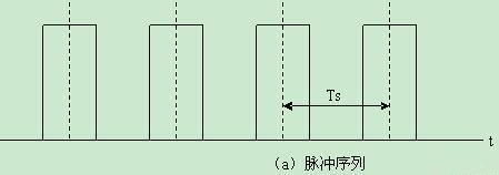
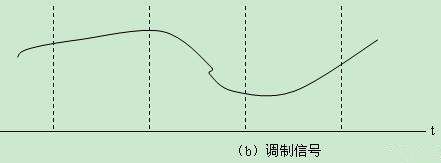
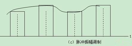
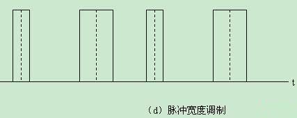
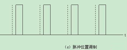
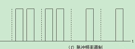
Figure 1 Schematic diagram of pulse modulation
As can be seen from Figure 1, the pulse modulation is not a complete instantaneous value of the transmitted modulated signal, but only those instantaneous values ​​of the transmitted modulated signal at intervals of a certain time interval (i.e., period Ts); these instantaneous values ​​are called sample values, such as (b) The vertical line segment is shown. The process of taking a sample value from a continuous signal is called sampling. Therefore, pulse modulation must first sample the modulated signal and then use each sampled value to control a certain parameter of the pulse sequence. Since the modulated signal itself is continuously varied, the magnitude of the sampled value may be any value. That is to say, each sample value is discrete in time, but has continuous properties in terms of value (amplitude, width, position, frequency), which are discrete analog signals in time. Thus, the above several types of pulse modulation can be collectively referred to as analog pulse modulation.
Digital modulation is not only discrete in time, but also discrete in value. This signal is called a digital signal. Instead of transmitting the true value of each sample, it transmits an approximation of each sample. To this end, the quantization process must be sampled first, that is, several (finite number) of standard values ​​(called quantized values) are predetermined, and the quantized value closest to the real sample is selected therefrom instead of the real sample value.
Why do you want to quantify it? The reason is:
(1) During the transmission process, noise and interference are always mixed. At the receiving end, no matter whether it is a human or an electronic circuit, there is no strong discriminating power to distinguish the details of the signal. Thus, no matter how accurate the sampled values ​​are sent, the receiving end is unable to recover the actual sample values ​​after all, so it is not necessary to accurately transmit the true sample values.
(2) If the quantized value is transmitted, even if noise and interference are mixed in the transmission process, as long as it is not too large, it is not enough to increase or decrease the received quantized value to another adjacent quantization. Level, the receiver can easily determine which quantization level is being sent and re-reproduce it accurately. This fundamentally eliminates noise and interference during transmission.
(3) Usually, a set of pulse codes is used to represent the quantized values ​​of each sample. This process is called pulse coding. Since the quantized value is a finite number, the number of sets of different pulse codes required is also limited, which is achievable. However, if the actual sample value is to be transmitted by the pulse code without quantization processing, since there are an infinite number of actual sample values, it is necessary to represent them with an infinite set of different codes, which is obviously impossible. Therefore, only quantization makes pulse coding possible, and coding is an important measure for digitizing analog signals and improving the effectiveness of digital signal transmission.
In digital electronic technology, digital pulse modulation belongs to source coding, and there are many specific solutions. Two of the more important ones are Pulse Code Modulation (PCM) and Delta Modulation (DM). The former uses a set of electrical codes composed of a plurality of pulses to represent the quantized value of each sample; the latter is a special case of the former, each set of pulse codes consists of only one pulse, but it does not represent the quantized value of each sample, Rather, it indicates the polarity of the increment between two adjacent sample values, or it indicates the rate of change of the signal.
In summary, sampling is a common feature of pulse modulation (except pulse frequency modulation), and quantization is a unique feature of digital pulse modulation. Nowadays, most applications are digital signals. The replacement of analog signals by digital signals is an inevitable trend in the development of electronic technology.
Third, the sampling and sampling theorem
The analog signal is sampled to obtain time-separated sample values. Can these values ​​be used to uniquely and completely represent the original continuous signal?
To answer this question, let's look at a simple example. If you want to draw a continuous experimental curve, it is well known that it is generally not necessary to continuously measure each experimental data, but only need to measure a number of discrete data for the abscissa. Each data traces a point, and as long as the points are dense enough, a smooth experimental curve can be made from them. This curve uniquely and accurately represents the experimental results. According to experience, we know that if the curve changes more slowly, the point can be made thinner; if the curve changes sharply, the point should be made denser. As can be seen from this crude example, a continuous function can be replaced by some discrete values ​​(sample values), but these samples should be dense to a certain extent. So, how long should the sampling of the continuous signal be short, or to what extent should the sampling rate (or sampling frequency) be high, in order to recover the continuous signal from each sample? The sampling theorem answers this question.
Sampling theorem: Assume that the highest frequency of a signal spectrum with a limited frequency band is fM. If the sampling frequency fs is equal to or greater than twice the maximum frequency fM of the signal, the original signal can be recovered by sampling without distortion. 2fM is called Nyquis. The special frequency, sampling interval Ts is 1 / (2fM).
The sampling theorem specifies the minimum sampling speed, that is, at least two samples should be taken in one cycle corresponding to the highest frequency of the signal spectrum. Thus, it is not necessary to transmit the signal itself, as long as the discrete samples of the transmitted signal are transmitted, the original continuous signal can be recovered from the samples at the receiving end.
Fourth, from analog TV to digital TV
Analog TV signals become digital TV signals. First, analog-to-digital conversion is performed. As mentioned above, it is necessary to sample and quantize the analog signals. The continuous analog signal is sampled and processed to obtain the actual sampled value. After the actual sampled value is quantized, it becomes a signal that is discrete in both time and value, and is an approximate sampled value. Commonly used binary to represent the sample value, the sample value is represented by a set of pulse code, this process is called coding.
![]()
Figure 2 Block diagram from analog signal to digital signal
1. Quantification
Quantization is the stratification (or grading) of the entire amplitude range that a signal may have. Each layer is a standard level, called the quantization level, as shown by the horizontal lines in Figure 3. For the sake of simplicity, only eight quantization levels are taken in Figure 3, which are 0, 1, 2, 3, 4, 5, 6, and 7, respectively. The difference between adjacent quantization levels is called the quantization step or quantization interval, which is equal to 1/8 of the total signal amplitude. Figure 3 also shows the signal and its five samples with numbers 1, 2, 3, 4, 5, etc., the actual sample values ​​are 1.6, 4.4, 6.4, 5.8, 3.6. We are not transmitting these actual sample values, but the values ​​of the 8 quantization levels that are closest to the actual sample values, ie, 5 values ​​such as 2, 4, 6, 6, and 4. Here is an approximate approach, the same as the rounding approximation in arithmetic operations.
Figure 3 Quantification of the signal
Obviously, the quantized value shown as a circle in FIG. 3 is only an approximation of each true sample value, and the error existing between them is called a quantization error. It is not difficult to see that the maximum quantization error is half of the quantization step, that is, the large error is 1/16 of the total signal amplitude. The quantization error has a random nature because the difference between the transmitted quantized value and each actual sampled value is completely unpredictable. The constant occurrence of quantization error forms an interference noise called quantization noise. In order to reduce the quantization noise, it is necessary to increase the number of quantization levels, that is, to reduce the quantization interval. However, the more quantization levels are obtained, the more different sets of pulse codes are used to transmit them, and the more pulses are required for each set of codes. This requires an increase in the transmission speed or an increase in the bandwidth. Therefore, you should choose the appropriate number of quantization levels, not too large, and not too small. For example, selecting 128 quantization levels requires a 7-bit binary code to represent each quantization level (27 = 128).
Since the maximum quantization error is always half of the quantization interval, for small signals, the ratio of signal to quantization noise is greater than the ratio of signal to quantization noise for large signal conditions, which is disadvantageous for small signals. In order to overcome this disadvantage, non-uniform quantization can be used, that is, in the case of small signals, the level is made denser (or the quantization interval is made smaller), and in the case of large signals, the quantization interval is made larger. Accordingly, in the receiver it should be extended to restore the proportion of the original signal.
2, coding
Encoding is the representation of each quantization level by an integer, a set of quantization levels corresponding to a set of integers. Thus, the signal waveform is changed to a set of numbers corresponding to the respective sampling timings, that is, the signal waveform is digitized. These numbers can be represented in binary and can be transmitted in binary code accordingly. The so-called binary code is a group of electrical pulses, each pulse has only two levels (0 and 1 for unidirectional pulses, +1 and -1 for bidirectional pulses), and each group of pulses of different arrangement is combined. Can represent different integer numbers represented by binary. For example, 8 quantization levels are represented by a 3-bit binary code. Each pulse position corresponds to a 1-bit binary number, called 1 bit. The three sets of pulses represent a value called a three-bit code. Obviously, since there are two possible states of the pulse, there should be 23=8 different arrangements of the three pulses, and there should be 24=16 different arrangements of the four pulses. The different arrangement of the N pulses should be There are 2N species. That is to say, a set of codes (i.e., N-bit codes) composed of N pulses can represent 2N different values.
In addition to binary codes, more than two multi-level pulses can be used for encoding. The number of levels that each pulse can take is M, which is called M-ary code. In the M-ary code, if there are N pulses in each group, they can be used to represent MN different quantized values. This is because there are M possible values ​​for each pulse amplitude, so N pulses can have different combinations of MN types.
3, secondary digital modulation
The above-mentioned analog signal to digital signal is one-time modulation, and the digital baseband signal is obtained, which can be transmitted through a cable or an optical cable by using a dedicated digital television device. In order to save power and improve frequency band utilization under certain reliability and quality requirements, the digital baseband signal needs to be secondarily digitally modulated to achieve multi-path signal multiplexing, and then the secondary digital modulation signal is up-converted to wired. TV band.
The secondary digital modulation is to use the digital baseband signal to modulate the parameters (amplitude, frequency or phase) of the RF sinusoidal oscillation. Therefore, the secondary modulation has three forms of amplitude modulation, frequency modulation and phase modulation, including amplitude keying (ASK) and frequency shifting. Key modulation (FSK), minimum frequency shift keying (MSK), phase shift keying (PSK), quadrature amplitude modulation (QAM), X-ary residual sideband modulation (VSB) and other modulation methods. PSK is divided into 2PSK, QPSK, and 8PSK; QAM is divided into 4QAM, 16QAM, 64QAM, and 256QAM. Different modulation methods, digital system effectiveness (band utilization) and reliability (bit error rate) are different, so it is very important to choose which digital modulation method.
Quadrature amplitude modulation, phase shift keying, and vestigial sideband modulation are often used in digital televisions, which have extremely high spectrum utilization and are the primary modulation method for transmitting multiple digital televisions in a standard television channel.
4, the advantages of digital signals
(1) When transmitting over long distances, each relay station can completely reproduce the received digital signal, thereby fundamentally eliminating noise and interference during transmission. Each relay station re-transmits a signal with no noise (of course, quantization noise is always present). That is to say, the interference mixed in the signal transmission process between the relay stations does not accumulate.
(2) The modulation and demodulation circuits are digital circuits, which are well suited to utilize the logic design of the integrated circuit, so the reliability and stability are high.
(3) Digital signals are easy to store.
(4) It is possible to reduce unnecessary duplication of message signals and perform digital compression.
(5) Appropriate coding can reduce the effects of noise and interference. The ratio of the signal to the quantization noise (power ratio) is increased by 6 decibels for each additional bit, which means that the widening of the signal bandwidth can improve the signal-to-noise ratio.
Fifth, the digital system block diagram
The digital system block diagram is shown in Figure 4. At the transmitting end, the modulated signal m(t) is applied to the compressor to compress the signal with a larger amplitude to ensure a similar signal/quantization noise ratio for signals of different sizes. The sampling circuit samples the modulated signal processed by the compressor and then adds it to the multiplexer along with other channel signals that have undergone the same processing (ie, compression and sampling) to form a time division multiplexed signal. The two functions of quantization and coding are performed by an analog-to-digital converter that quantizes the sampled signals of each channel and transmits each quantized sample with a set of binary codes. At the beginning of the channel conversion, each code is transmitted to the channel in series, directly transmitted through the optical cable, cable, or secondary modulation, and modulated by the sinusoidal carrier and then transmitted through the transmitter.
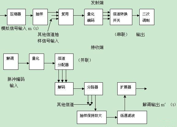
Figure 4 Digital system block diagram
At the receiving end, it may be a binary code transmitted directly from the optical cable or cable in series, or it may be a certain type of modulated wave received by the receiver. In the latter case, the binary code can be obtained after demodulation. After the binary code enters the quantizer, the noise and interference mixed in the transmission process are removed, and the relatively pure binary code is re-formed. The splitter splits each binary code into a parallel transmission to the decoder. The decoder is a number-mode transponder that converts each group of codes into corresponding pulses of a certain height. Therefore, each channel signal corresponds to one amplitude modulation pulse, and each amplitude modulation pulse is time division multiplexed together. The splitter separates the amplitude modulation pulses and transmits them to the sampling and amplification circuits of each channel, so that the height of each pulse is maintained in one sampling period, so that the amplitude modulation pulse becomes a staircase wave, which is transmitted. An approximate waveform of the modulated signal after preprocessing. The low-pass filter filters the quantization noise and reduces the staircase wave to a continuous signal, which is still the modulated approximation waveform after the transmitter is preprocessed. The expander removes the distortion of the modulated signal caused by the compressor of the transmitting end, and thus obtains the final output signal m'(t), which is an approximation of the original modulated signal m(t).
If it is transmitted by fiber optic cable, since most of the output terminals of the electric transmitting terminal are bipolar codes with positive and negative polarities, this type of pattern is not suitable for driving the optical transmitter. Optical transmitters are light intensity modulated and require unipolar pulse drive. Therefore, a bipolar to unipolar pattern interface needs to be added between the electro-transmitter and the optical transmitter.
Now, a dedicated digital TV transmission system is available, which can transmit uncompressed TV and 32-channel stereo through optical cable. If other devices are configured, it can also transmit MPEG-2 multi-channel compressed TV signals. The system can select one group E1 (2Mb) and three group E3 (34Mb) interface boards to transmit data and telephone. It can also be connected with the SDH network to make data, cable TV and communication triple play.
Sixth, digital system performance parameters
1, transfer rate
The frequency at which a binary digit appears is the number of digits of a binary digit transmitted per unit time, called the transmission rate. The transmission rate is used to measure the efficiency of the digital system, and there are two representations of symbol rate and information rate.
(1) The symbol rate is also called symbol rate, digital rate, and key rate. It refers to the number of symbols transmitted per second. The unit is “Baud†and is represented by Ds. When the digital signal is expressed in binary, it is called the binary symbol rate; when the digital signal is expressed in multiple digits, it is called the M-ary symbol rate.
(2) Information rate, also known as bit rate, refers to the number of information units transmitted per second, in bits per second (bit/s or b/s or bps), expressed as Rb.
The relationship between symbol rate and information rate is:
Rb=Ds×Log2M
In the formula M - the symbolic number.
In particular, when M = 2, Rb = Ds, that is, the symbol rate is equal to the information rate.
2, Eb / No
Eb/No is used to measure the transmitted signal quality and represents the ratio of the energy per bit Eb of the useful signal to the single sideband noise density No.
After the analog/digital conversion of the analog signal, the part in the middle of any two quantization levels will be slightly different from the signal converted from the subsequent digital/analog, which is equivalent to superimposing a noise on the original signal, called quantization. noise. The quantization noise is white noise, which is consistent with the law of noise superposition. There are also various disturbances and noises during the transmission.
Assuming a binary digital signal s(t) whose symbol width is T, the energy per bit of the signal is:
Eb=2(t)dt
In actual engineering calculations, the energy per bit is often obtained by dividing the transmit power of the transmitter by the information rate.
3, frequency band utilization
Band utilization is an important indicator of the efficiency of a digital system. It refers to the transmission rate that can be achieved in a unit of bandwidth, in bit/s/Hz or b/s/Hz.
The transmission of a digital signal, like the transmission of an analog signal, requires a certain bandwidth. The digital signal is a different permutation combination of "1" and "0", for example, it may be either 1 or 0, or 0 and 1 may alternately appear, and is usually a disorderly combination of 0 and 1. The digital signal of 0 and 1 alternately has the highest spectral component, and the bandwidth of the waveform in Fig. 5(a) is larger than the bandwidth of the waveform in (b).
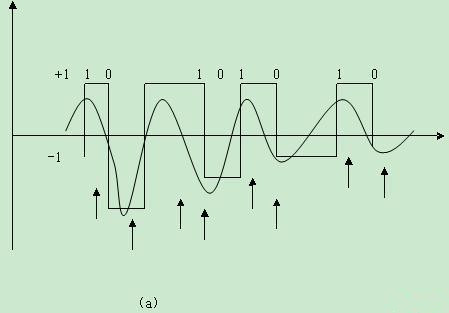
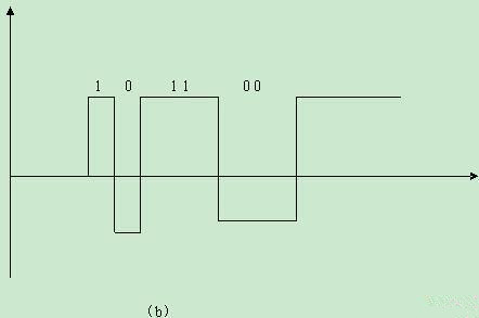
Figure 5 The highest frequency of the pulse code modulated signal
At the receiving end, in order to recover the pulse coded signal without error, it is only necessary to correctly distinguish whether it is 1 or 0 at each moment shown by the arrow in Fig. 5 (the positive and negative of the pulse are used to represent 1 and 0, respectively). If the signal is passed through a low-pass filter, the bandwidth of the low-pass filter is just enough to pass the sine wave shown in the figure. The frequency of the sine wave is equal to the repetition frequency of the pulse waveform in the figure, that is, the binary numbers 0 and 1 appear. Half the frequency. At this time, the receiving end can correctly distinguish 1 and 0 according to the sine wave output from the filter. Therefore, in order to be able to recover the original waveform without error at the receiving end, the required frequency bandwidth should be at least equal to half the frequency at which the binary digit appears.
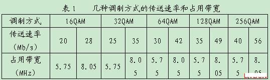
When comparing the efficiency of a digital system, it is not acceptable to look at the transmission rate alone. Because different modulation methods are used, even if the transmission rate is the same, the occupied bandwidth is not the same, as shown in Table 1.
4, bit error rate and bit error rate
When the sender sends "1", the receiver receives "0"; or when the transmitter sends "0", the receiver receives "1". The case where the transceiving codes are inconsistent is called an error.
There are many reasons for errors, including the effects of noise and pulse jitter, industrial interference and lightning interference. There are many factors that affect the size of the bit error rate, such as the signal modulation method, and the level of the threshold is determined. The smaller the bit error rate, the higher the video signal-to-noise ratio is required. For example, in order to achieve a bit error rate of 10-9 for a digital system, the signal-to-noise ratio is required to be about 21.6 dB.
(1) The bit error rate is used to measure the reliability of the correct transmission of the signal by the digital system, and refers to the probability that the binary symbol is misdirected, which is usually represented by Pe. Under the condition of transmitting a large number of binary symbols:
Pe = the number of binary symbols that were misdirected / the total number of symbols in the binary digital stream
(2) The bit error rate is also used to measure the reliability of the correct transmission of signals by the digital system. It refers to the probability that a symbol or symbol (which can be binary or M-ary) is misdirected. It is usually expressed by Pes.
The bit error rate and bit error rate are different, and the values ​​are equal only in binary. The digital signal can be expressed in binary or in M. Since there are many binary representations, there is no unique correspondence between the bit error rate and the bit error rate.
For a natural binary code, the bit error rate is smaller than the bit error rate, and the correspondence between the bit error rate and the bit error rate is:
1/2<Pe/Pes<2/3
For binary Gray code, the correspondence between bit error rate and bit error rate is:
Pe=Pes/n
Where n=Log2M
The modulation method is different and the frequency band utilization is different. See Table 2.
It is known from Table 2 that the PES of 2PSK, QPSK and MSK is small, the reliability of correctly transmitting signals is high, but the frequency band utilization is low; the other multi-level modulation method improves the frequency band utilization, but reduces the reliability of correctly transmitting signals. .
5, jitter performance
Jitter is a transient instability in the transmission of digital signals. It represents the deviation of the moments of the digital signal from the standard time position. The jitter includes two aspects, one is that the input signal pulse changes around an average position; the other is that the extracted clock signal changes left and right at the center position, and the jitter phenomenon is equivalent to phase modulation of the digital signal. If such an signal is observed with an oscilloscope, a low-frequency interference modulation occurs on the leading and trailing edges of the stable pulse pattern, and the frequency is generally 0-2 KHz. When the jitter is severe, the receiver mistakes the pulse for no pulse (or vice versa) due to the pulse shift. The higher the transmission rate of the system, the greater the impact of jitter.
There are many reasons for the jitter. In addition to the performance of the timing extraction circuit, it is also related to the state of the input signal. When a long "0" code appears in the input code stream, timing extraction is difficult and timing jitter is generated. In a system of level relays, the jitter generated by each repeater also accumulates, which deteriorates performance.
Since the jitter is difficult to completely eliminate, in actual engineering, some system's maximum jitter index is often proposed as a constraint on jitter.
Function: The LED Aluminum Flashlight has 3-5 modes;
Feature: The LED Aluminum Flashlight usually high power and super bright;
Trait: The products are waterproof, shockproof and tactical;
Method of application: Simple on/off push button operation;
Range of application: The LED Aluminum Flashlight for emergency events, camping, outdoor activities and indoor;
Adervantages: Our products are saled with factory price, and the quality can guarantee, lastly we provide warranty for 1 year.
LED Aluminum Flashlight
Aluminum Led Flashlight,Aluminum Torch,Electric Focus Led Flashlight,Aluminum Portable Lights
Ningbo Henglang Import & Export Co.,Ltd , https://www.odistarflashlight.com