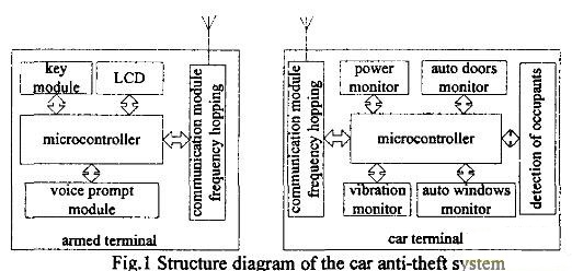
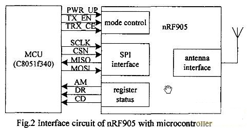
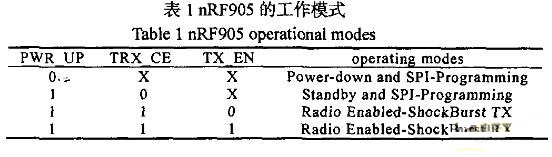
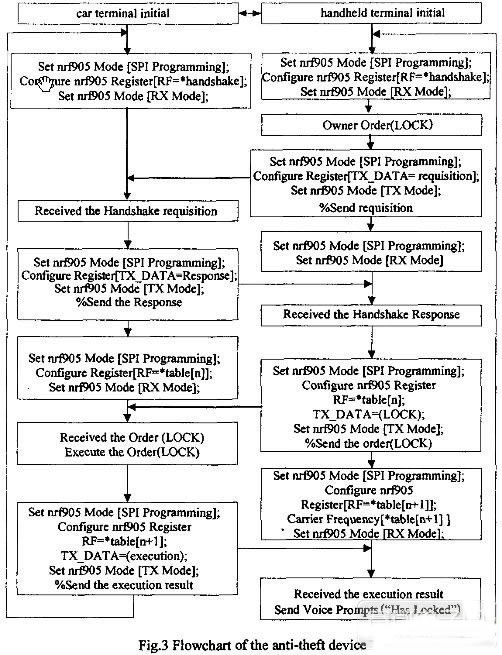
Abstract: In order to solve the problem that the existing ordinary automobile electronic anti-theft device is easy to be cracked and duplicated by fixed frequency communication, a new anti-theft device is designed by using the RF transceiver chip nRF905 with carrier frequency modulation function. The anti-theft device is in the process of communication. Constantly changing the communication frequency, so that the information can not be interfered or intercepted, the anti-theft device is difficult to be copied and cracked, and the reliability of the frequency hopping communication is increased through the optimization and programming of the communication scheme. The increased two-way communication function enables the owner to grasp the car in time. The condition and alarm information, and the reliability of the anti-theft device are increased by the design of the multi-sensor detection circuit, and the test has achieved a good anti-theft effect. This article refers to the address: http:// 0 Preface With the development of social economy and the improvement of people's living standards, cars have gradually entered the family, and how to effectively prevent car theft has become a concern of car owners. At present, in the automobile anti-theft device, the ordinary electronic remote-controlled anti-theft device occupies a large market share due to the low price. However, ordinary electronic remote control alarms are mostly fixed carrier frequency communication, which is easy to be interfered, intercepted and cracked. It has been reported that a general remote lock can be copied by a dedicated decoder within 30 seconds, and can be cracked within 1 minute. Ordinary electronic remote control alarms are mostly one-way communication, the owner can remotely lock and unlock the car, but the car information cannot be timely feedback to the owner. In view of the shortcomings of ordinary electronic anti-theft devices, we apply the frequency hopping communication technology applied in military communication to the design of automobile intelligent remote control anti-theft device. In the process of communication, the communication frequency of both parties is constantly changed, so that information transmission is difficult to be tracked, interfered or intercepted, and cracked, which will effectively improve the security and reliability of the anti-theft system. 1 system overall design The system consists of two parts: the vehicle terminal and the human terminal. The vehicle terminal mainly completes the receiving and executing of the man-machine control command, executes the car unlocking command, and completes the detection and transmission of the car anti-theft information; the person-holding terminal mainly completes the transmission of the control command of the car owner to lock and unlock the car, and receives Vehicle-related alarm information and instruction execution information sent from the vehicle terminal. The system function structure is shown in Figure 1. Figure 1 system overall structure block diagram 2 system circuit design and implementation 2.1 Circuit design of vehicle terminal The vehicle terminal mainly completes the monitoring of the car anti-theft information and sends the car abnormal condition information to the owner, and the receiving executor holds the terminal control command, such as locking and unlocking the car, etc., and the current anti-theft device mainly relies on the vibration sensor to detect the theft information is unreliable. The sensor circuit with multi-information fusion is designed to improve the reliability of the anti-theft device by monitoring the door, window and car seat. The added standby power management function ensures that the anti-theft device can still work normally when the main power line is cut. It is mainly composed of main control MCU module, wireless frequency hopping communication module, automobile door and window monitoring, power supply monitoring, vibration detection, and whether there is a monitoring module in the car. 2.1.1 main control MCU module circuit The main control MCU is mainly responsible for the coordinated control of the whole system, the detection and processing of sensor information, the configuration of the frequency hopping communication module, and the transmission and reception of information, etc., which are implemented by C8051F340. The C8051F340 is a mixed-signal system-level integrated chip from Cygnal Corporation of the United States. It has an 8051-compatible high-speed CIP-51 core. It integrates analog and digital peripherals and other functional components commonly used in data acquisition and control systems. The internal clock frequency can be used. Up to 48MHz. With an enhanced SPI interface, it is easy to control the nRF905. 2.1.2 frequency hopping communication module hardware circuit The hardware circuit of the frequency hopping communication module is realized by the single-chip RF transceiver chip nRF905 from Nordic. Its power consumption is very low. The current is only 11mA when the output power is output at –10dBm, and the current is 12.5mA in the receiving mode. The transmission distance is greater than 100m. Works on 433/868/915MHz 3 ISM channels (can be used free of charge). nRF905 can automatically complete the processing of header and cyclic redundancy check, can automatically complete Manchester encoding/decoding by on-chip hardware, communicate with microcontroller using SPI interface, configuration is very convenient, performance is reliable, and manual carrier frequency can be realized. Control, with 128 selectable frequency points, frequency spacing 100kHz, frequency switching time of 650μs, can quickly achieve frequency point switching. The chip can be used to form a transceiver module for wireless frequency hopping communication. The module circuit and the single chip interface circuit are shown in Fig. 2. The working mode configuration is realized by connecting PWR_UP, TRX_CE and TX_EN with the single chip microcomputer. Carrier detection, address detection, and interrupt detection are performed by CD, AM, and DR. The carrier frequency, communication command data format configuration, and data reception are realized through communication with the single-chip microcomputer through the SPI interface. Figure 2nRF905 and microcontroller interface circuit 2.1.3 Door window monitoring module By placing the photodetection diode at the door window of the door, when the door or door and window are not locked, the corresponding photoelectric detection circuit will detect relevant information, and the vehicle terminal notifies the automobile micro-processing system through the vehicle main control interface when no one is inside the vehicle. The automatic closing door closing circuit is started, and the owner's door or window is not locked, and an alarm signal is issued when the door window is opened in the anti-theft state. 2.1.4 There is no undetected module in the car Through the pressure measuring device designed by the strain resistor placed under the seat of the car, it is judged whether there is any person in the car, such as no one in the car, the car anti-theft lock system is not activated, and the lock is automatically locked for 1 min; if the car anti-theft lock is activated, If there is someone, it is possible that someone has stolen the car and the alarm immediately gives an alarm. 2.1.5 Off-board vibration detection module The vibration detection outside the vehicle is used to detect whether a person collides with the car when the vehicle is in an anti-theft state, and if so, an alarm. It uses vibration sensor Z04B, which is a high-sensitivity vibration module, which can detect extremely weak vibration waves; it is easy to install and is not restricted by any angle; it has good anti-interference, no response to external sound, and has anti-lightning and firecracker interference. Capability, output is a transient pulse used to form a reliable automotive vibration detection module. 2.1.6 Power Measurement and Control Module The standby power management function is designed to improve the safety and reliability of the anti-theft system when the main power supply of the vehicle is cut off, the backup power supply is supplied and the situation is fed back to the owner. 2.2 Circuit design of the person holding the terminal The person holding the terminal completes the control command transmission of locking and unlocking the car, and receives the relevant information of the car sent by the vehicle, such as the vibration situation, the information of the door window switch status, and issues a voice prompt. The main control single-chip circuit and the frequency hopping communication module and the human-machine interface module are composed, wherein the main control single-chip circuit and the frequency hopping communication module are identical to the vehicle-mounted terminal part. The human-computer interaction interface module circuit mainly performs the transmission of the human operation command by the button circuit, and the LCD liquid crystal display circuit is used to make the operation more convenient. The ISD1820 design voice prompt circuit is used for the alarm prompt and the vehicle terminal instruction execution prompt. 3 system software design and implementation 3.1nRF905 configuration process and implementation of frequency hopping communication 3.1.1 nRF905 configuration process As shown in Figure 2, the nRF905 controls the four operating modes of the three pins PWR_UP, TRX_CE and TX_EN of the nRF905 through the CPU to determine its four operating modes (as shown in Table 1), through the CD, AM, and DR of the nRF905. The pin performs carrier detection, address detection, and interrupt detection. In the first two modes in Table 1, the MCU configures five internal registers of the nRF905 through the SPI interface (status register, RF configuration register, transmit address register, transmit data register, Receive data register). The status register includes data ready pin status information and address matching pin status information; the radio frequency configuration register contains transceiver configuration information such as frequency and output functions; the transmit address register contains the address of the receiver and the number of bytes of data; The transmit data register contains information of the data packet to be transmitted, such as the number of bytes, etc.; the receive data register contains information such as the number of bytes of data to be received. 3.1.2nRF905 wireless transceiver process 1) Launch mode setting and process a) After power-on, the MCU first configures the nRF905 mode. First, set PWR_UP, TX_EN, and TRX_CE to the (10X) configuration mode. b) The MCU transfers the frequency configuration data of the RF register through the SPI, and the configuration data is moved into the nRF905 module. c) When the MCU has data to be sent to the specified node, the address (TX-address) and valid data (TX-payload) of the receiving node are transmitted to the nRF 905 through the SPI interface. d) The MCU sets TRX_CE, and TX_EN is a high start transmission. e) nRF905 internal processing: wireless system automatic power-on, data packet completion (plus preamble and CRC check code), data packet transmission (1000kbps, GFSK, Manchester code). 2) Receive mode a) After power-on, the MCU first configures the nRF905 mode. First, set PWR_UP, TX_EN, and TRX_CE to the (10X) configuration mode. b) The MCU transfers the frequency configuration data of the RF register through the SPI, and the configuration data is moved into the nRF905 module. c) Set TRX_CE high, TX_EN low to select RX mode, nRF905 monitors airborne information. d) Carrier detection (CD) is set high when nRF905 finds and receives the same carrier frequency. e) When the nRF 905 receives a valid address, the address match (AM) is set high. f) When the nRF 905 receives a valid data packet (the CRC check is correct), the nRF 905 removes the preamble, address and CRC bits, and the data ready (DR) is set high. g) The MCU sets TRX_CE low and enters standby mode (standby mode). h) The MCU can read valid data through the SPI interface at an appropriate rate. i) When all valid data is read, nRF905 sets AM and DR low. 3.1.3 Implementation of frequency hopping The nRF905 can realize manual carrier frequency control. It only needs to modify the CH_NO and HFREQ_PLL of the RF working frequency register of the nRF905 to select different carrier frequencies to achieve frequency hopping. The bit variable HFREQ_PLL is 0, indicating that it operates in the 430MHz band, and the channel difference is 100kHz. If it is 1, it means that it operates in the 868/915MHz band with a channel difference of 200kHz. Therefore, there are 1024 communication frequencies. The communication frequency (H) is H = (422.4 + (CH_NO) 10/10) × (1 + HFREQ_PLL). For example, CH_NO=(001001100)2=(76)10, HFREQ_PLL=0, then H=(422.4+76/10)×(1+0)=430.0MHZ. The system is uniformly set to operate in a frequency band of 430 MHz, the channel difference is 100 kHz, each frequency point interval is 100 kHz, the random number is generated between 0 and 128, the frequency hopping bandwidth is 12.8 MHz, and a frequency hopping time T ≤ 800 μs is completed. Time: 2011-06-27 11:00 Author: Information and Electronic Engineering Source: Unknown 3.2 Reliability Design and System Implementation of Remote Control Alarm Based on Frequency Hopping Communication 3.2.1 Generating a random frequency hopping table to enhance security In order to increase the security, each pair of password locks has a unique corresponding 32-bit encrypted address, and a corresponding one-to-one random frequency hopping table is added. When the first time is used, the setting switch corresponding to the vehicle and the human-machine is turned on. The terminal can generate a random frequency hopping table, and send the hopping frequency table to the vehicle terminal through the handshake frequency. When the return verification is correct, the frequency hopping table is stored in the power-off protection non-volatile FLASH memory, and is turned off. The setting switch ensures the safety of the frequency meter while ensuring that the two machines have a corresponding frequency hopping frequency table, as long as the two parties agree on the values ​​of CH_NO and HEFREQ_PLL which are consistent with the frequency hopping table. Frequency hopping communication can be realized, which increases the reliability and security of wireless communication. 3.2.2 Set handshake and error, packet loss return frequency, and ensure reliable communication A prominent problem with frequency hopping communication is that although the reliability is high, once the communication between the two communication parties is wrong, the data read by the frequency hopping table is inconsistent, and the system will be confused and unable to communicate. In order to solve this problem and improve the security and reliability of the anti-theft device, the system sets a fixed frequency as the handshake frequency, and the communication between the human-machine and the vehicle is first connected from a handshake frequency set by both parties. This frequency only carries the target address and handshake request or response signal, even if intercepted does not affect the security of the system. When there is a problem in the system, if the communication is unsuccessful, immediately return to the handshake frequency and restart communication from the initial value of the hopping table. The interrupt is masked during the transmission of an instruction information to ensure reliable transmission of information. 3.2.3 System working process After the system initializes the frequency hopping table, both the HMI and the car machine configure the nRF905 register (ConfigureRegister) to set the system's working mode (SetnRF905Mode) to work in the handshake frequency and receive mode (RXMode). When one end receives the interrupt request (the owner's command/alarm information, etc.), the handshake request is initiated. After the handshake is completed, the frequency hopping communication process is performed twice, and the information is sent and fed back. During the sending process, the sender sends a handshake. The time to wait for a response or feedback after a request or an instruction does not exceed 200 ms. Otherwise, the communication is considered to be in error and the initiator re-initiates the request. Taking the driver's lock command as an example, the whole working process of the system is shown in Figure 3. The sending process of other car owners' command and the sending of car alarm information are similar. Figure 3 anti-theft device work flow chart 4 Conclusion The reliable communication distance of the system in the cell can reach 150m, which meets the practical application requirements of the general car alarm. The frequency hopping communication ensures that the anti-theft device is not easily intercepted and cracked. The optimized design of the communication scheme ensures the frequency hopping. Communication reliability further improves the security and reliability of the anti-theft device. The system can also be used for motorcycle anti-theft and other anti-theft systems after simplifying the peripheral circuit design.
The Co-Al Co-doped Barium Titanate
Lead-free Piezoelectric Ceramics was successfully developed by Yuhai company
through repeated experiments. By Researching the influence of Co-Al Co-doping
on the structure and properties of Barium Titanate-based piezoelectric
ceramics, the formulation and preparation technology of Barium Titanate-based
piezoelectric ceramics were optimized. Yuhai`s BaTiO3 was prepared by conventional
solid-phase sintering method, with the piezoelectric constant d33 (>170pC/N),
dielectric loss tgδ≤0.5% and mechanical coupling coefficient Kp≥0.34.
Barium titanate lead-free piezoelectric
ceramics are important basic materials for the development of modern science
and technology, which was widely used in the manufacture of ultrasonic
transducers, underwater acoustic transducers, electroacoustic transducers,
ceramic filters, ceramic transformers, ceramic frequency discriminators, high
voltage generators, infrared detectors, surface acoustic wave devices,
electro-optic devices, ignition and detonation devices, and piezoelectric
gyroscope and so on.
Application: military, ocean, fishery, scientific research,
mine detection, daily life and other fields.
China Patent of Yuhai company`s BaTiO3
Chinese Patent No.: ZL 2011 1
0126758.6
Name: Lead-free Barium Titanate
Piezoelectric Material with Addition of Cobalt and Aluminum
Lead free piezo material BaTiO3
Lead-free Material
Properties
BaTiO3
Dielectric Constant
ɛTr3
1260
Coupling factor
KP
0.34
K31
0.196
K33
0.43
Kt
0.32
Piezoelectric coefficient
d31
10-12m/v
-60
d33
10-12m/v
160
g31
10-3vm/n
-5.4
g33
10-3vm/n
14.3
Frequency coefficients
Np
3180
N1
2280
N3
Nt
2675
Elastic compliance coefficient
Se11
10-12m2/n
8.4
Machanical quality factor
Qm
1200
Dielectric loss factor
Tg δ
%
0.5
Density
Ï
g/cm3
5.6
Curie Temperature
Tc
°C
115
Young's modulus
YE11
<109N/m3
119
Poison Ratio
0.33
Lead Free Piezoelectric Elements Piezo Element,Piezo Ceramic Elements,Piezoelectric Ceramic,Pzt Tubes Zibo Yuhai Electronic Ceramic Co., Ltd. , https://www.yhpiezo.com