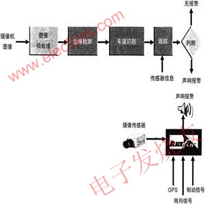
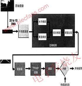
Car safety has received more attention from people, and the application of high-tech in automobiles has emerged one after another. The lane departure warning (ldw) system is an example. Experts pointed out that about 50% of car accidents are caused by deviation from the normal driving lane. The main reason is that the driver is upset, inattentive or fatigued. The ldw system will alert the driver when the vehicle is driving at a high speed, the car is deviating from the normal driving lane, allowing the driver to correct the driving route in time. This is another safety device installed in the car after the seat belt and safety airbag. System overview Figure 1 is a schematic diagram of the ldw system. A front-facing camera monitors the road on which the vehicle travels, with a range of 50-70 feet. Typically, one or more CMOS image sensors provide multiple images of the road that are connected to multiple video ports of the processor. Here video-based signal processing replaces the analog signal chain. This processing method not only improves the accuracy of the system, but also saves the material cost of the system. Figure 1 Schematic diagram of ldw system and external connection After the data enters the system, it is transformed into a processable format in real time. Within the processor, the preprocessing is first performed to filter out the noise mixed during image capture. The position of the vehicle relative to the roadway marking line is then detected. The input information stream of the road image is transformed into a series of lines that outline the surface of the road. Look for the edge in the data field to find the lane markings. These edges actually form the boundary where the vehicle should travel forward. The processor must keep track of these marking lines to determine if the driving route is normal. Once the vehicle is found to inadvertently deviate from the roadway, the processor outputs a signal to drive the alarm circuit to make the driver correct the driving route immediately. The alarm can be in the form of a buzzer or a horn, or a language prompt, and a vibrating seat to alert the driver. The ldw system also takes into account the brakes and steering that the car normally uses. These devices can affect the work of ldw and complicate the system. Therefore, the ldw system does not work during slow running or braking, normal steering. work process Figure 2 depicts the workflow within the processor in more detail. In general, the ldw system has two major functions, namely the discovery of edges and tracking, the former used to determine the lane markings; the latter allows the vehicle to travel along the normal lane. Before performing digital processing, smooth filtering is first required. Since image sensors are not ideal, meteorological conditions, ambient temperature, vehicle motion, and electromagnetic interference all introduce noise into the image acquisition process, and the noise blurs the image. More specifically, it is originally in the same grayscale in the original image. The pixels of the value are in different gray values ​​in the noise image. In addition to noise, there is also the effect of quantization errors, which cause the edges of the edges to fall on multiple pixels, which also makes the boundaries less clear. Noise and quantization errors are uncontrollable, so it is very difficult to filter and smooth the input view. Without this step, it is very difficult to find clear road signs. Smoothing the digital video stream should also take into account that the video stream is a sequence of real images that vary at a specified rate. The image filter should operate at a fast enough speed to keep up with the continuous reception of the input image. Therefore, the image filter kernel is critical to optimizing the execution of the minimum number of possible processor cycles. An effective filtering method is to use a basic two-dimensional convolution operation. Figure 2 ldw system internal image processing algorithm flow The next thing to do is edge detection. The so-called edge refers to the part of the image where the local brightness changes most significantly. For digital images, the gray value of the image can be represented by a gradient, and the sobel operator is a commonly used edge detection algorithm. The edge of the discovery identifies the sign of the roadway. This process involves the hough transform. It is one of the basic methods for identifying geometric shapes in image processing. The most basic hough transform is to detect straight lines from black and white images. It maps the pixels on the image plane to points on the reference plane (ie a buffer) and determines the parameters of the line by statistical properties. The hough transform calculates a sinusoidal curve for each pixel in the input image, so the computational effort is large and techniques are needed to speed up the calculation. First, some calculations can be calculated in advance, so they can be used as reference values ​​by lookup tables. Secondly, make some reasonable assumptions about the position and nature of the roadway sign in the input image, that is, if only those points of the potential roadway sign are calculated, a large number of unnecessary operations can be avoided, thereby simplifying Calculate and improve quality. The output of the hough transform is a set of straight lines, some of which may be lane marking lines. Since many of the highway system's roadway markings are standardized, a defined set of rules can exclude certain lines from the candidate lane markings. Finally, this set of possible lane markings is used to determine the location of the vehicle. . Lane tracking Lane information comes from a variety of possible sources of information in a car that combine with measured relevant parameters (such as speed, acceleration, etc.) to aid lane tracking. According to the measurement results, the lane system makes an intelligent judgment, that is, whether an unintentional departure of the vehicle route occurs. In more advanced systems, other parameters such as time, road conditions, and driver alertness can also be modeled. Predicting lane geometry is a tricky problem that is often solved by kalman filters predicting the curvature of the road. The kalman filter predicts the state of the future and uses it to calculate the parameters of the next post to reduce the computational load in the hough transform. Once the processing framework is established, the system designer can add his own ip in each decision step in the processing thread. The simplest system should take into account the properties of the vehicle during the judgment process. For example, an alarm that suppresses lane change when steering or using a brake. In other words, the system should be able to determine whether the lane change is intentional or unintentional. More complex systems can also involve gps coordinate data, travel routes, time, climate, and other parameters. Application Iteris was one of the first companies to develop the ldw system. Its autovue ldw system is a self-installing kit that includes wiring harnesses, horns, switches, connectors and cables. It is said that it can be installed within three hours under normal circumstances. It is suitable for most of the D-type 1930 data bus type 8 trucks used in North America. The three major European manufacturers evobus gmhh, mercedes-benz omni busse and man busse have also approved this product. InfiniTI has developed a new ldw system with a small camera mounted on the front windshield, speed sensor, indicator and audible alarm. The company plans to equip it on the popular fx off-road suv. The company is also preparing to deploy the ldw system in the next-generation luxury m45 performance sedan. Mobileye's ldw system uses a monocular image processor to determine the lane markings of the road and to measure the position of the vehicle relative to the marking line. It is characterized by the ability to detect a variety of marking lines, solid, dashed, box and cat eyes. Where there is no marking line, the system uses the road boundary line to determine the position. The system fits three road model parameters of lateral distance, slope and curvature to improve the reliability of the alarm. The system also works on rainy days and nights.