Abstract: A safe visual reversing system is designed based on the embedded Linux operating system using S3C2440 microprocessor as the control chip. The USB camera is driven by the embedded Linux operating system kernel to monitor the situation behind the vehicle in real time, and the voice alarm module is activated to remind the driver to pay attention by comparing the ultrasonic ranging result with the threshold. It is verified by experiments that the system runs stably and the captured video images are clear and real-time, which can meet the requirements of visual reversing. This article refers to the address: http:// Introduction Electronic information and digital image processing technology has been widely used in various fields. The informationization of in-vehicle systems has become an important symbol of the modern automobile industry. The current reversing radar system can provide a lot of help for the driver. Most of them use ultrasonic ranging technology to directly display the distance between the tail and the obstacle. However, due to the scattering properties of the ultrasonic waves, if the ground has sharp protrusions or there are angular objects that lie across the air, the system cannot effectively "perceive". If you can add a visual function to the existing reversing system, the driver can clear the situation behind the car without having to look back when reversing. This paper designs a visual safety reversing system. The system uses the embedded Linux operating system kernel to drive the USB camera to realize the real-time monitoring of the after-vehicle condition. The voice alarm function is activated by judging whether the ultrasonic ranging has reached the threshold. 1 system design As shown in Figure 1, the system consists of the main control module, ultrasonic transceiver module, USB camera image acquisition module, voice alarm module and LCD display module. The main control module adopts Samsung's ARM9 core-based S3C2440 microprocessor, with a maximum frequency of 533 MHz and fast processing speed. The software programming technology is used to realize the control of its peripheral circuits, and provide various signals required by the peripheral circuits, which simplifies the design difficulty of the peripheral circuits. 2 system hardware design 3 system software design This paper chooses the embedded Linux operating system. It has the characteristics of cutting, kernel stability, powerful function, and support for multiple hardware platforms. First, a cross-compilation development environment is built on a PC (host) equipped with a Linux operating system, and the S3C2440 control module is used as a target board. Then, the C language with better portability is used to write the underlying driver and top-level application required for the design on the PC, and then the cross-compilation debugging tool is used to compile and link to generate executable code, and finally transplant to the target board. This design is to use the MiniGui to load jpeg to realize the real-time display of the USB camera to capture the image. Added support for the jpeg library when compiling the program. The idea of ​​programming is to continuously capture images from the camera and store them in /tmp/l. In jpg. In the Linux GUI user support system MiniGUI, the image is loaded by the loadbitmap function, and the image is not automatically updated after loading, and cannot be based on 1. The change of jpg changes automatically. Therefore, in the program to set a timer, refresh the screen every 100 ms, basically real-time update. The s3c2440_sonar_open() function is used to open the device. The s3c2440_sonar_rcad() and s3c2440_sonar_write() functions are used to read and write devices. The s3c2440_sonar_re-lease() function completes the release of the interrupt. The s3c2440_sonar_ioctl() function is used to control the timing interrupt and ranging values ​​in the device. The copy_to_user() function and the put_user() function are used to implement data transfer. The device is opened under the application to realize data transfer between the kernel state and the user state. The module initialization function s3c2440_sonar_init() implements device initialization, interrupt initialization and processing, device registration, and so on. Static void s3c2440_sonar_exit() is used to interrupt interrupt, release resources, etc. when the module is unloaded. After the command is synthesized, it can be sent to the XF-S3011 module. In the embedded Linux system, first open the XF-S3011 device file, then write the command frame to the file, and finally close the device file. Conclusion This paper adopts embedded Linux operating system and Samsung S3C2440 microprocessor designed visual and voice alarm as one integrated safety reversing system, which has high practical value. In the process of displaying the video image processing, the distance between the tail and the obstacle can be measured by the ultrasonic wave, and when the distance measurement value is less than the preset distance, the voice will prompt the driver to give an alarm. It has been verified by experiments that the system is stable in operation and allows the driver to accurately grasp the road conditions behind the vehicle and improve the safety of reversing.
Key words: S3C2440; video image acquisition; ultrasonic ranging; voice alarm 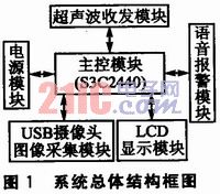
2.1 Main Control Module The composition of the hardware platform of the main control module with S3C2440 as the core is shown in Figure 2. 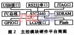
2.2 Ultrasonic Transmitting Circuit The schematic diagram of the ultrasonic transmitting circuit is shown in Figure 3. The transmitting circuit is mainly composed of an inverter 74LS04 and an ultrasonic transmitting transducer T1, and uses a 40 kHz square wave signal output from a PWM timing counter inside the CPU. 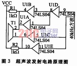
One way is sent to one electrode of the ultrasonic transducer (1 pin of T1) through a first-stage inverter (U1C is connected in parallel with U1E); the other is through two-stage inverter (U1D is the first stage, U1B and U1A constitutes the second stage) and is sent to the other electrode of the ultrasonic transducer (2 feet of T1). By applying the square wave signal to both ends of the ultrasonic transducer by this type of push, the emission intensity of the ultrasonic wave can be increased. Two inverters are connected in parallel at the output to improve the drive capability. The upper resistors R1 and R2 can improve the driving capability of the inverter 74LS04 to output a high level on the one hand, and enhance the damping effect of the ultrasonic transducer on the other hand.
2.3 Ultrasonic receiving circuit The schematic diagram of the ultrasonic receiving circuit is shown in Figure 4. The CX20106A is a dedicated chip for infrared detection reception and is commonly used in TV infrared remote receivers. The advantages are simple and easy to use, simple circuit connection, and reduced the trouble of production debugging. When the CX20106A receives a 40 kHz signal, it will generate a low-level falling pulse on pin 7, which can be connected to the ARM external interrupt pin as an interrupt signal input. 
2.4 USB camera image acquisition module USB digital camera using Zhongxing Microelectronics ZC0301 chipset. Compared with the analog camera, its advantages are: CMOS image sensor can directly generate image raw data; hardware supports standard JPEG compression; with mainstream high-speed USB bus device interface. For the camera, the type of information transmission on the USB bus is usually transmitted in real time. The USB device side provides several communication ports, and a logical communication channel is established between the host and the port for data transmission. During the device initialization phase of the camera, the host communicates with port 0, and the driver detects the camera model and all port information. Entering the data transmission phase, the host establishes a communication pipeline with the detected real-time input port, and returns the image data captured by the camera in real time.
2.5 Voice Alarm Module and LCD Display Module The voice alarm module uses the XF-S3011 Chinese speech synthesis chip produced by Anhui Zhongkeda Information Technology Co., Ltd. It is a single-chip processor designed for embedded applications with the ability to synthesize arbitrary Chinese text. The XF-S3011 receives commands and data sent by the host computer through the serial port (UART). The commands and data are encapsulated and transmitted in the form of frames. The maximum length of data allowed to be transmitted is 200 bytes. Its drive circuit is designed with a triode drive. When the distance measured by the ultrasonic wave is less than the set threshold, the control command is sent to the XF-S3011 by the S3C2 440, and a voice alarm is activated to alert the driver. The display module uses Donghua's 3.5-inch TFT LCD (with a resolution of 320×240) and uses the Frame Buffer device under embedded Linux to drive the LCD.
3.1 Video image acquisition and LCD display program design Step l, using the USB camera driver spca5xx that dynamically loads the ZC0301 chip. The driver source code consists of four parts: the initialization module of the device module, the uninstall module, the upper software interface module, and the data transfer module. Unzip it under kernel/driver/usb and patch it. When compiling the system kernel, make make menueonfig in the kernel directory of arm linux; select Video for linux under Multimedia device under <*>, load Vide04linux module, provide programming interface function and related data structure for video capture device; (M ) Select the SPCA5XX item.
Step 2, use Linux Video4linux to access the USB camera device, capture video images, and capture real-time data streams. The program flow is shown in Figure 5. 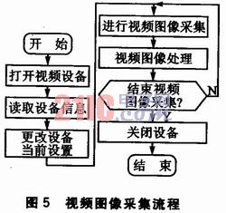
Define the data structure for the program: 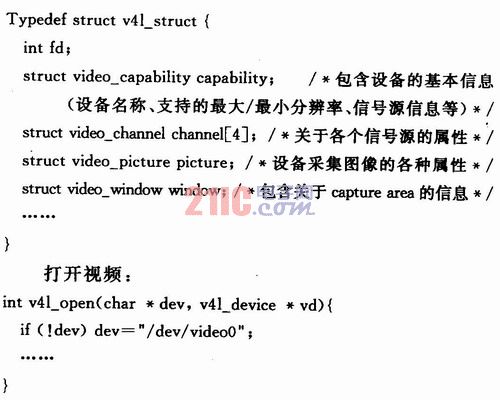
3.2 Ultrasonic Ranging Driver Design The function of the ultrasonic generation program is to generate a square wave with an ultrasonic signal frequency of approximately 40 kHz by the PWM timing counter. Use Timer0 and turn Timerl on for timing. The main program of the ultrasonic range finder uses the external interrupt to detect the returned ultrasonic signal, and once it is found, it immediately enters the interrupt routine. Immediately after entering the interrupt, the Timerl is stopped and the ranging success flag is assigned a value of 1. The program flow is shown in Figures 6 to 8. 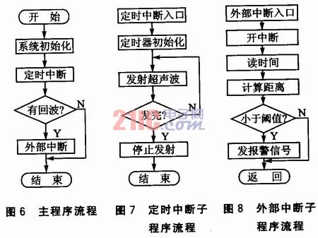
When the main program detects the flag of successful reception, the distance between the tail and the obstacle can be obtained by the following formula (the speed of sound C at 20 °C is 344 m/s):
S=(C·T1)/2
Where T1 is the count value of the counter Timerl.
This part of the program can be designed as a character device driver under Linux. To use the Linux system to provide a data structure of the device driver interface function struct file_operations, to achieve the opening, reading, writing, releasing and control of the ultrasonic sensor device. The initialization of the timer and external interrupt related registers and the setting of parameters are all done in the open() interface function. Defined in this device driver. The data structure of file_operations is: 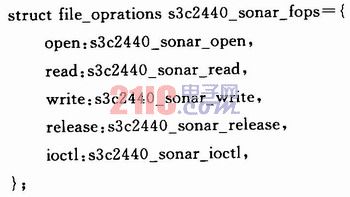
3.3 Voice Alarm Program Design When the measured distance value is less than the threshold value, the S3C2440 sends a control command to the XF-S3011 to start the voice module. The part of the code that makes up a speech synthesis command frame is as follows: 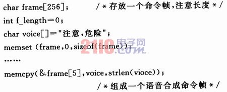
![]()