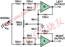
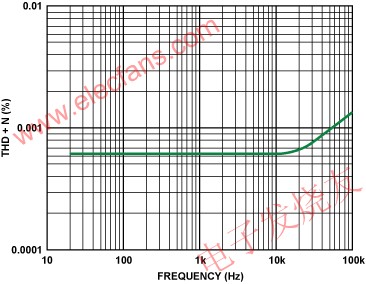
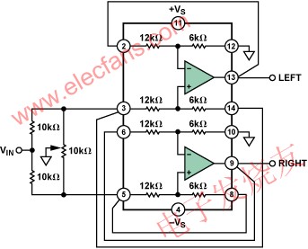
Figure 1 shows an audio Panpot circuit that responds to potentiometer settings by continuously changing the position of the mono audio signal between the left and right stereo channels. Low cost and low distortion are important considerations for audio circuits. The AD82731 dual low distortion differential amplifier uses an internal gain setting resistor to ensure excellent match between the two channels. It requires no external components and each channel is configured as two high performance amplifiers with a gain of 3. In the audio range, the total harmonic distortion is less than 0.0007%. This article refers to the address: http:// Although this circuit can be built in a discrete manner, integrating amplifiers and resistors on a single chip can bring many benefits to board designers, such as better performance specifications, smaller PCB area, and lower production costs. Figure 1. Audio Panpot Amplifier In this circuit, the signal is distributed between the two amplifiers through a 10 kΩ series resistor. Insert a vernier grounded potentiometer between the two non-inverting inputs. The combination of a potentiometer and a 10 kΩ resistor forms a light load that is easily driven by most sources. The gain of the amplifier is configured to 3. When the potentiometer cursor is at either end, one input is grounded, so no signal is sent to the corresponding output. The other input has a voltage of VIN/2, so its output is 1.5 × VIN. When the cursor is in the middle position, the inputs of both amplifiers are VIN/3, so the output of each amplifier is VIN. Thus, by moving the cursor (mechanically or electronically), the signal level on one channel changes continuously from 0 to 1.5 × VIN, and the signal level on the other channel changes continuously from 1.5 × VIN to zero. For the listener, the sound source seems to move from one channel to another between the sound levels. Therefore, the apparent source of the sound image or sound can be located anywhere between the left and right speakers. Figure 2. Total harmonic distortion and noise versus frequency Figure 2 shows the total harmonic distortion and noise over the entire audio range. The error increases with increasing frequency, but the total error is still less than 0.0007% at 20 kHz. Figure 3 shows the connection diagram of the IC. Figure 3. Connection diagram