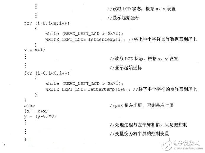
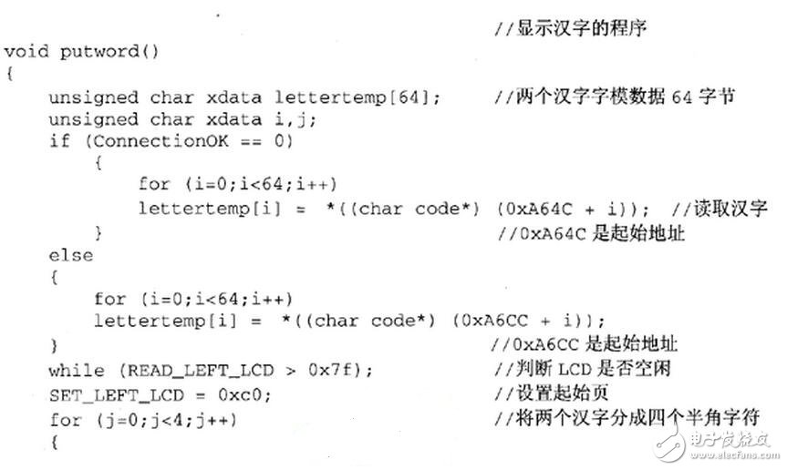
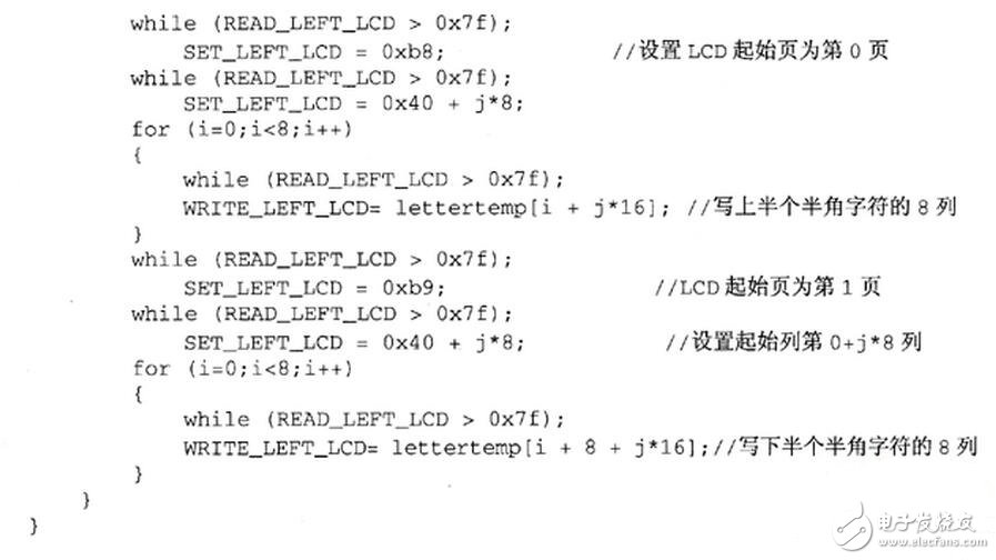
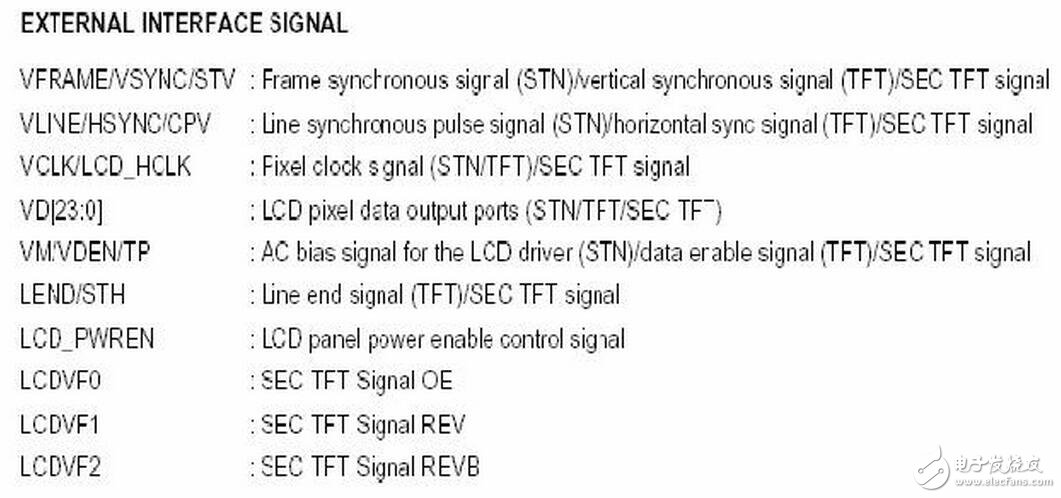
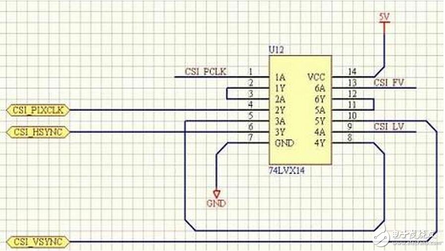
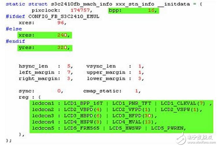
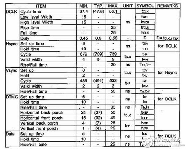
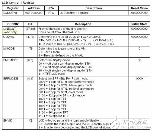
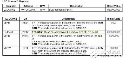
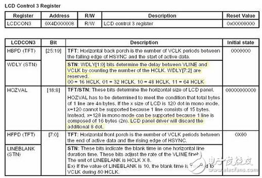
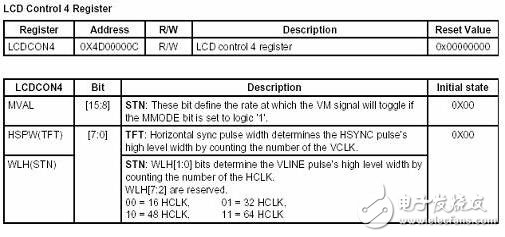
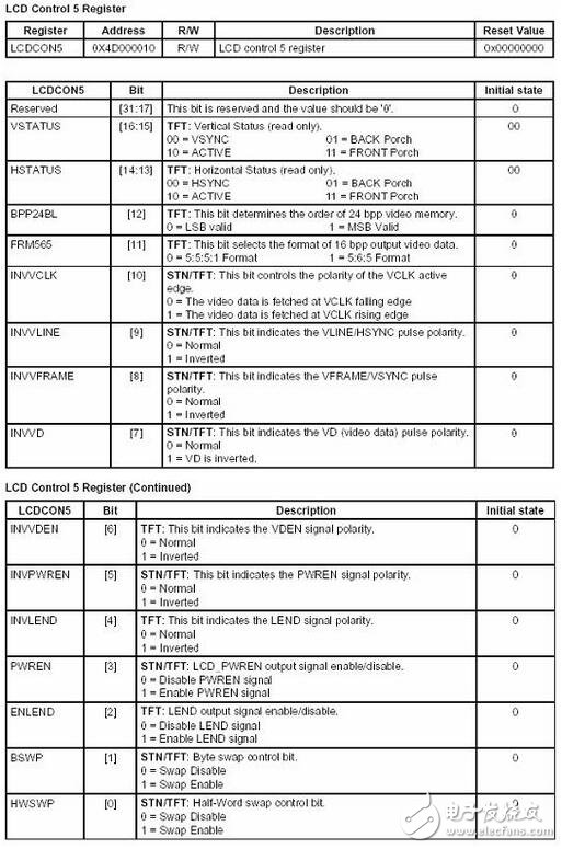
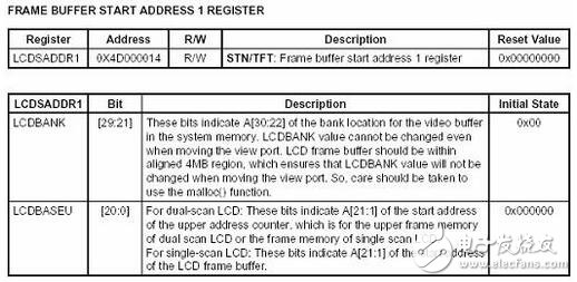
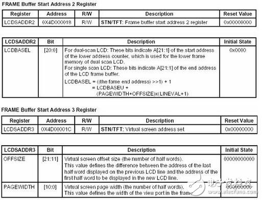
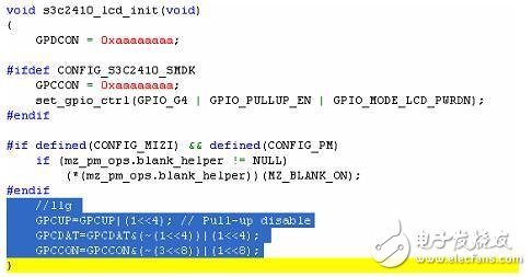
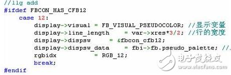
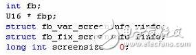
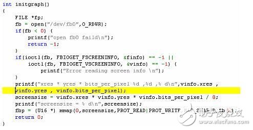
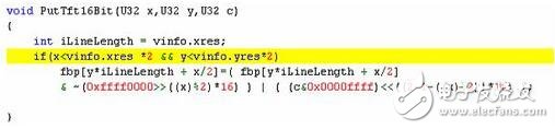
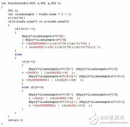
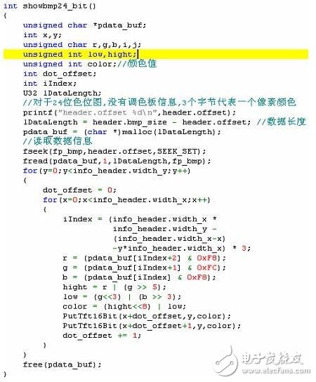
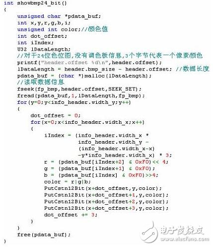
The subroutine of the display part of the system is associated with the font data structure. Here, the ASCII character display subroutine and the subroutine displaying the Chinese character font separately are listed. According to these two subroutines, the display program implementation principle of the display part can also be seen. In this subroutine, x refers to the Chinese character line, which can only be 0 to 3 total 4 lines; y refers to the half-width character column, which can only be 0 to 15 total 16 columns, so it can be in any one-half character position on the screen. An ASCII half-width character is displayed on it. When dealing with Chinese characters, the Chinese characters are treated as two half-width characters. When displaying, a Chinese character is displayed in the order of upper left, lower left, upper right, and lower right. The following shows the Chinese character subroutine. at this point. It can be seen from the program that when j=0, the upper left and lower left of the first Chinese character are written, and then in the loop of j, the upper right and lower right of the first Chinese character are displayed in turn, and the second Chinese character is displayed. Upper left and lower left, the upper right and lower right of the second Chinese character. In fact, the start page of the LCD indicates the 8 lines of the initial display, that is, the upper half of a half-width character. This is the process of displaying partial Chinese characters. 1. In order not to let everyone feel boring and let friends understand better, I will use an example to describe the S3C2410 next driver (the initial source code of this article is based on s3c2410fb.c provided by Huaheng) and simple The preparation of the GUI program. 2. To get an LCD, first connect the LCD control lines with the LCD control signals of the S3C2410. Of course, the power supply must be connected. Otherwise, don't look for me. Also need to pay attention to the following points: 1) Backlight: For most color LCDs, it must be connected to the backlight, so that we can see the contents of the screen; 2) Control signals: Different LCD manufacturers have different names for control signals. The S3C2410 chip manual also gives multiple names for a signal (Figure 1). It depends on the hardware engineers. Figure 1 Name and explanation of the control signals given in the S3C2410 manual VFRAME: Frame sync signal between the LCD Controller and the LCD driver. This signal tells the LCD screen that a new frame has begun. The LCD controller inserts a VFRAME signal immediately after the completion of a complete frame display to start the display of a new frame; VLINE: A line sync pulse signal between the LCD controller and the LCD driver that is used by the LCD driver to transfer the contents of the horizontal line (row) shift register to the LCD display. The LCD controller inserts a VLINE signal after the entire horizontal line (full line) of data is moved into the LCD driver; VCLK: the pixel clock signal between the LCD controller and the LCD driver. The data sent by the LCD controller is sent out at the rising edge of VCLK and sampled by the LCD driver at the falling edge of VCLK. VM: AC signal of the LCD driver. The VM signal is used by the LCD driver to change the polarity of the voltages of the rows and columns to control the display or extinction of the pixels. The VM signal can be synchronized to each frame or to a variable number of VLINE signals. 3) Data line: This is the RGB signal line that we are talking about. The S3C2410 chip manual has detailed instructions. Because of the space relationship, it is not excerpted here. However, it is necessary to cooperate with the hardware engineering. Method, 24-bit 16-bit or other. There are two ways to use a 16-bit TFT screen. Before writing the driver, you need to know whether it is 5:6:5 or 5:5:5:I. These are related to the writing of the driver. 4) Pay attention to the power supply voltage of the LCD. For handheld devices, it is usually 5V or 3.3V, or both 5V and 3.3V. If the required power supply voltage of the LCD is 5V, then pay attention to the logic of the S3C2410. The output voltage is only 3.3V. In this case, let your hardware engineers help to increase the logic output voltage of the S3C2410 to 5V. Otherwise, you may be able to light up the screen, but the displayed image will not be normal until the sun comes out from the west. Oh, I can eat it bitter! 5) 3.3V logic voltage is converted into 5V logic voltage circuit diagram 6) Finally, there is a problem. Some LCD screens also require a companion chip, which is the LPC3600 in the S3C2410 manual. This may be discussed in the manual of the LCD. I have not encountered such a screen, so it is not very clear. So is it that all the screens that need to connect with the S3C2410 need that nasty guy? This is a question that many people (including me) will have at the beginning, but most of the LCD screens now don't need this nasty guy. The control signal of the screen is directly connected to the control signal of S3C2410, at least. I have not encountered it before. 7) I have to remind everyone that the connection of S3C2410 to the LCD screen must not exceed 0.5 meters, otherwise it will cause trouble for you. I also suffered too much. The above part of the LCD screen shows that any information is correct. And only the bottom of the screen will be correct and sometimes wrong, toss for a while, only to know that the connection is too long! 3. Ok, with the help of the hardware engineer, the hardware is connected, then we should do the software work, write the driver. 1) Let us first look at the definition of RGB data structure Find the following information in s3c2410fb.c staTIc struct s3c2410fb_rgb xxx_tft_rgb_16 = { Red: {offset:11, length:5,}, Green: {offset:5, length:6,}, Blue: {offset:0, length:5,}, Transp: {offset:0, length:0,}, }; This is to define the RGB color of the 16-bit color, R:G:B:I = 5:6:5:0, which is the 565 display method we often say. Oh, in order to let some friends better understand, I have a few words, we just write a 16-bit data color data (for the convenience of analysis, I write it as a binary) RGB = 10101101 10111001 According to the above structure definition, let's analyze how much RGB is (because there is no transparent color, we will not analyze it) a) blue: {offset: 0, length: 5} The offset is 0 and the length is 5. We extract it from that RGB and it is "11001" b) green:{offset: 5, length: 6} The offset is 5 and the length is 6, we extracted from that RGB is 101 101 c) red: {offset: 11, length: 5 } The offset is 11 and the length is 5. We extract 10RGB from that RGB. d) We get an RGB value of 13:45:200, which is the color e) Then, in turn, what do we have with the value of RGB, because the effective number of bits of RGB is less than one byte (8 bits), then we can only reluctantly cut the love, discard the low-level data, the code is as follows r=(rDat&0xF8); g=(gDat&0xFC); b=(bDat&0xF8); Hight=r|(g"5"; Low=(g》"3)|(b""3); Color=(hight》》8)|low; Remember, this code is useful in GUI programs. 2) For 8-bit color (256 colors) data structure definition staTIc struct s3c2410fb_rgb rgb_8 = { Red: {offset:0, length:4,}, Green: {offset:0, length:4,}, Blue: {offset:0, length:4,}, Transp: {offset:0, length:0,}, }; This is the definition given in the original program, I feel a bit wrong, I think it should be R:G:B = 3:3:2 staTIc struct s3c2410fb_rgb rgb_8 = { Red: {offset:5, length:3,}, Green: {offset:2, length:3,}, Blue: {offset:0, length:2,}, Transp: {offset:0, length:0,}, }; Because I didn't go to debug in person, I don't have any say. I hope that friends who have done this will give me an answer. 3) For the CSTN screen, it can generally reach 12-bit color (4096 colors). The S3C2410 chip is also supported, but the work on the software is relatively large, because from the original code, we can not find any The 12-bit color shows signs, and Linux does not seem to support 12-bit color. If you want to do something simple, then you can write your own code. I am here to give a 12-bit color data structure definition. staTIc struct s3c2410fb_rgb xxx_stn_rgb_12 = { Red: {offset:8, length:4,}, Green: {offset:4, length:4,}, Blue: {offset:0, length:4,}, Transp: {offset:0, length:0,}, }; However, there is still some work to be done to complete the writing of the 12-bit color CSTN screen driver. I will introduce it to you later. 4) Then look at the code below, where the part to be modified has been marked in green, which is described below. a) Number of color bits Bpp:16 If your LCD screen is TFT, you can usually achieve 16-bit color or 24-bit color. It depends on how the hardware is connected. You can set it according to the situation. If your LCD screen is CSTN, according to the introduction of the conventional LCD manual, you can generally support 8-bit color (256 colors), and the actual CSTN screen can achieve 12-bit color (4096 colors). There is a big difference. If you want to choose a cheap screen and you need a rich color, it will take a little effort to complete the 12-bit color driver. b) LCD screen width and height Xres: 240 Yres: 320 Needless to say, this is how much the resolution of your screen is set. c) The setting of the registers is not difficult. Let's take a sip of the S3C2410 LCD registers in one bite! First introduce my screen, this is a Hitachi TFT screen with a size of 640X240, which can support 16-bit color. a table related to the drive Figure 2 LCD screen information With this information, let's take a look at the settings of the LCD registers. LCD controller 1 LINECNT --- This is a read-only data, of course we don't need to care about it CLKVAL --- This is a very useful parameter. In fact, it is not necessary to calculate the calculation behind it. We can get a valid value through the actual test. For a 320x240 screen, it is generally set to 7 and for 640x480. Screen, the value can be smaller. For the following calculation formulas and comments (STN: CLKVAL <<= 2, TFT: CLKVAL <<= 0), I don't know how to understand, because in the actual application I ordered a 640X240 CSTN screen, when my CLKVAL = 1 has achieved an optimal effect, which seems to contradict the instructions, I can not explain why? ! PNRMODE --- This should not need to be explained. Everyone can understand it. For TFT screen, it can only be set to 11, and for CSTN screen, it may need to be set according to the actual screen information. In 10, the 8-bit single scan mode. The instructions for 4bit single scan, 4bit double scan, and 8bit single scan are described in detail in the manual of s3c2410. You can refer to it. BPPMODE --- This parameter need not be said more, it is to set the color number of the screen 喽. The setting of these parameters is very simple, I give the definition of my screen: Lcdcon1: LCD1_BPP_16T | LCD1_PNR_TFT | LCD1_CLKVAL(1), At the same time, I also give a CSTN screen register parameter information. Lcdcon1: LCD1_BPP_12S | LCD1_PNR_8S | LCD1_CLKVAL(9), LCD controller 2 For the TFT screen, you have to fill it in. As for what to translate, I believe everyone is better than my level and translate it myself. I only explain how to "deduct" this value from the LCD. It's very easy. Take a look at the LCD screen data in Figure 2. Compare the following information: LCD2_VBPD: Vertical back porch typical value is 7 LCD2_VFPD: Vertical front porch typical value is 4 LCD2_VSPW: Vsync Valid width is typically 2 About LINEVAL will be mentioned later in the program, do not care here. After analysis, we know how to set up LCD2: Lcdcon2: LCD2_VBPD(7) | LCD2_VFPD(4) | LCD2_VSPW(2), For the STN (CSTN) screen, the setting of this register is the easiest. Set VBPD, VFPD, and VSPW to Zero. which is Lcdcon2: LCD2_VBPD(0) | LCD2_VFPD(0) | LCD2_VSPW(0), LCD controller 3 For TFT screens, it is easy to find HBPD and HFPD as follows LCD3_HBPD: Horizontal back porch is typically 37 LCD3_HFBD: Horizontal back porch is typically 32 For HOZVAL will also be mentioned later, here for the time being After analysis, we know how to set up LCD3: Lcdcon3: LCD3_HBPD(37) | LCD3_HFPD(32) , For the (STN) CSTN screen, I don't have a good understanding of the true meaning of WDLY and LINEBLANK. By changing the values ​​of these two parameters, I have not got a particularly noticeable difference. I generally set it to: Lcdcon3: LCD3_WDLY_16 | 0x10 , LCD controller 4 For the TFT screen, you need to set the value of HSPW, which is also very easy to get in the LCD manual. LCD4_HSPW: Hsync Valid width is typically 5 As for MVAL, I don't know what it means, what is the effect, I never move it, just take the initial value of it 13 After analysis, we know how to set up LCD4: Lcdcon4: LCD4_HSPW(5) | LCD4_MVAL(13) , For the STN (CSTN) screen, like WDLY, I usually don't change it, because the change has not found any effect, this is the code in my driver, several screens are the same: Lcdcon4: LCD4_WLH(0) | LCD4_MVAL(13) , LCD controller 5 This register looks complicated, but nothing more than these: Read-only information: VSTATUS and HSTATUS Read-only stuff, setting it up is useless, don't bother. Color information of the TFT screen: BPP24BL, FRM565 The color information of the TFT screen, which we have already mentioned in the hardware connection of the LCD, sets the information according to the specific wiring method. Control signal polarity TFT/STN screen control signal polarity: INVVCLK, INVVLINE, INVVFRAME, INVVD, INVPWREN, PWREN The polarity of the control signal specific to the TFT screen: INVVDEN, INVLEND, ENLEND This information is mainly the problem of the signal output polarity of the S3C2410 and the input polarity of the LCD screen. It needs to be set according to the specific hardware. The polarity of the vline/hsync and VFRAME/VSYNC pulses is more common. Byte exchange control bits for color information: BSWP, HWSWP These two bits are used to control byte swapping and halfword exchange. They are mainly used for the problem of size and size. If the Chinese characters output to the screen are interchanged, or the image output to the screen is displayed, you can change this option. The specific meaning is described in detail in the S3C2410 chip manual. The information of my TFT is set as follows: Lcdcon5: LCD5_FRM565 | LCD5_HWSWP | LCD5_PWREN , a piece of CSTN screen information Lcdcon5: LCD5_BSWP | LCD5_PWREN , FrameBuffer start register 1 The setting of this register is not necessary to modify (TFT/STN), and the default code can be used: FrameBuffer start register 2 and FrameBuffer start register 3 The setting of these two registers is more important. Here I give the setup code for the 12-bit color CSTN screen and the 16-bit color TFT: The aforementioned LINEVAL and HOZVAL are given in source code, where the CSTN 8-bit color has not been tested. RGB Loopup Table Register These three registers need to be used when driving the 256-color CSTN screen. I have used it on other chips because this chip supports 12-bit color, so I did not debug it. Two sets of possible values: On S3C44B0 rREDLUT = 0xFCA86420; rGREENLUT = 0xFCA86420; rBLUELUT = 0xFFFFFA50; On Jupiter rREDLUT = 0xFEC85310 rGREENLUT = 0xFEC85310 rBLUELUT = 0xFB40 5) Well, the setting of each register is completed. Finally, when driving the CSTN screen, you need to remind everyone that there is a signal line called VM/DISP in the signal pin of CSTN. The function of this signal line is to open the display of LCD. Switch it to display, it can be connected to any GPIO port. A VM signal is provided in the S3C2410. This signal of the LCD can be connected to the VM signal of the S3C2410. Then, the following statement (blue selected part) must be added to the driver: Otherwise your LCD may not display anything (this statement is not needed for TFT screens) 6) There is still some work to be done on the driver of the 12-bit color CSTN screen. I will briefly introduce it here: a) First, write a fbcon-cfb12.c and fbcon-cfb12.h. These two files are very simple. Aren't fbcon-cfb16.c and fbcon-cfb12.h provided in armLinux? Simply modify it; b) Add the compilation of fbcon-cfb12.c to Config.in (if you don't, go to google and search, or take a look at my other article "JFFS2 on HHARM2410", there are some instructions) and define An FBCON_HAS_CFB12 parameter (emulated FBCON_HAS_CFB16 呗); c) In addition, you need to add support for 12-bit color in the corresponding part of s3c2410fb.c. Oh, it's simple to say, but there may be some problems in doing it. Give you a trick: find the code like #ifdef FBCON_HAS_CFB16 in the program, and simply understand the support for 12-bit color. d) I only give the changes in the function s3c2410fb_set_var, the other should not be very difficult, I believe friends can get it. e) Don't ask for source code with me, otherwise the boss will be upset. 4. The driver is written, re-Make, and download it. If all goes well, there will be a nice little 蜻蜓 (should be 蜻蜓) on the TFT screen or the 256-color CSTN screen. Note that it is not the case that your driver is OK, but you should use the GUI program for further testing. Because one or several parameters are incorrect, you can still see the small ones, but when displaying the graphics. There is a problem. In addition, when driving CSTN to 12-bit color, we can't see a small flaw on the screen (I didn't see a small flaw on my N-block CSTN screen), I think, maybe armLinux itself does not support 12-bit color display. , or some of our reasons for not doing the right thing, but this does not mean that your driver has a problem, use the GUI program to write FrameBuffer, see if you can get the right results. 5. Writing the GUI program The FrameBuffer driver is written, so how to use it, how to display the image on the LCD? This is the task of the GUI program. In fact, it is necessary to display the image on the LCD. To put it plainly, it is enough to write the data (including the color) to the corresponding position in the FrameBuffer. If you use a GUI such as Microwinow, MiniGui, Qt, there is no need to care about how FrameBuffer maps to points on the LCD screen, but if you are using a CSTN screen and want to display good photos, choose CSTN. 12-bit color (4096 colors), then you have to write your own GUI program, because it seems that armLinux (Linux) itself does not support 12-bit color. I heard that MiniGui supports 12-bit color, but my requirements at work are only Show graphics only, did not go deep into the MiniGui, so I wrote it myself. In addition, my friends are forgiven for not giving me all the source code, because I am employed by people after all, some Dongdong can be GPL, and some Dongdong can not be GPL for the time being. Here are some of the code for my program, I hope to help my friends. 1) Definition of global variables: Define several global variables for your convenience. 2) Initialize the graphics display engine to map fb0 to the buffer of the GUI Use the mmap function to associate a segment of user space with the device memory (FrameBuffer). Whenever a program reads or writes within an allocated address range, it is actually access to the device, and mmap can be used to quickly and easily access the memory of the display card. For applications with more stringent performance requirements like this, direct access can make a big difference. However, I have helped a user debug a GUI program on S3C44B0. In his GUI, the mmap function always fails. Because he did not get his hardware and driver source code, he did not analyze the reason, so he had to use the write function. Write data directly to fb0. The strange thing is that only writing a part of the data doesn't seem to have any effect, only the whole screen data is written. This can be more painful, but fortunately, he only writes black and white data, the amount of data is not very large, if the color is really painful. In addition, I would like to say a few more words, the correspondence between the pixel points of FrameBuffer and the pixels on the LCD screen, a deeper understanding of the understanding of the program may be more clear. We know that the black and white (2 color) color can be represented by 0 and 1, that is, 1 bit of data can be used, and 1 byte can represent 8 bits of data. If this byte is 10101010, the offset address of FrameBuffer If it is 0, 4 black dots will be displayed on the LCD screen, and 4 white dots will appear in the middle of the black dot (if 1 is black); for 4 colors, 00, 01, 10, 11 can be displayed. Four colors, that is, two bits of data can represent one bit of data, which is also 10101010, which corresponds to the display on the LCD screen. Is a line with a color value of 10 and a length of 4 (8/2); for the same reason, for 8-bit color (256 colors), 8-bit data can represent the color value of a point, and 10101010 is only on the LCD screen. Can be displayed as a point with a color value of 10101010. With the above foundation we can understand this statement very well: Screensize = vinfo.xres*vinfo.yres*vinfo.bits_per_pixel/8; That is, the size of FrameBuffer = the width of the LCD screen * the height of the LCD screen * the number of bits per pixel / the number of bits per byte For example, a 320*240 black and white flat, the size of the FrameBuffer is 320 * 240 * 1 / 8 = 9600 (bytes) The size of a FrameBuffer of a 320 * 240 16-bit color LCD is 320 * 240 * 16 / 8 = 153600 (bytes) 3) TFT screen 16-bit color drawing function With the drawing point function, what are you still thinking about? Graphic Chinese characters can be done! 4) CSTN screen 12-bit color point function Note that in order to make writing easier, I define fbp as static char * fbp in this function, and fbp is defined as U16 * fbp in the 16-bit color point function of the TFT screen. You can modify it as needed. 5) The 24-screen bitmap function is displayed under the 16-bit color of the TFT screen. The format of the Bmp file can refer to some information on the Internet, and you can find it directly if you need it. 6) CSTN screen displays 24-color bitmap function under 12-bit color 7) Oh, don't forget to turn off the device. Void closegraph() { Munmap(fbp,screensize); Close(fb); } reward: 1. The power supply voltage of the LCD is generally 5V or 3.3V for handheld devices, or 5V and 3.3V. If the required power supply voltage of the LCD is 5V, then it should be noted that the logic output voltage of the S3C2410 is only 3.3V, at this time, let your hardware engineers help to increase the logic output voltage of S3C2410 to 5V. Otherwise, the screen cannot be lit. 2, S3C2410 to the LCD screen must not exceed 0.5 meters, otherwise there will be problems. For example, the part above the LCD screen shows that any information is correct, and only the bottom of the screen will be correct and sometimes wrong. 3, 8-bit color data structure definition: Static struct s3c2410fb_rgb rgb_8 = { Red: {offset:5, length:3,}, Green: {offset:2, length:3,}, Blue: {offset:0, length:2,}, Transp: {offset:0, length:0,}, }; R:G:B = 3:3:2 4, CLKVAL determination: CLKVAL --- This is a very useful parameter. In fact, it is not necessary to calculate the calculation behind it. We can get a valid value through the actual test. For a 320x240 screen, it is generally set to 7 and for 640x480. Screen, the value can be smaller. 5. When setting LCDCON5, the polarity of the signal is controlled by the TFT/STN screen, so that the signal output polarity of S3C2410 is converted and the input polarity of the LCD screen is consistent.
AU Optronics Corp. (hereafter called AUO). AUO is the world's largest liquid crystal display (TFT-LCD) design, development, manufacturing and marketing company. Au Optronics is listed on the Taiwan Stock Exchange. AUO delivers advanced display integration solutions with innovative technologies, including 4K2K ultra-high resolution, 3D, ultra-thin, narrow bezels, transparent displays, LTPS, OLED, and touch solutions. AUO also has the most complete generation of production lines from 3.5G, 4G, 4.5G, 5G, 6G, 7.5G to 8.5G, providing a wide range of LCD applications in the size range of "1.2 to 71" TFT-LCD Panel. AUO is the world's leading TFT-LCD panel manufacturer, with a 16.2% market share for large-size panels. Au is committed to providing customers with a highly value-added portfolio of innovative products, utilizing the competitive edge of a complete generation of production lines, flexible adjustment and development of a variety of application products to further grasp the market opportunities and achieve a synergy niche.
Auo Tft,Auo Tft Display,9 Inch Lcd Screen,10.1 Inch Lcd Display Tonya Display Limited , https://www.tydisplay.com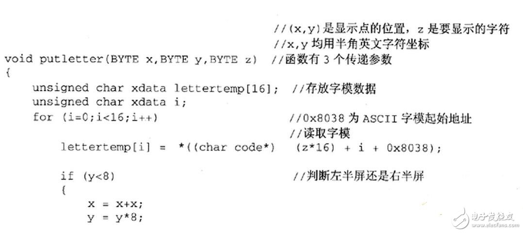
How to carry out the transplantation of LCD driver and its GUI simulation, the actual principle of LCD digital-to-analog conversion and its source code
How to design the LCD font display program?