Some of my customers are asking two questions at the same time: "Can you ensure that the CCD and LCD have no dead pixels and no bright spots?" It must be stated here that the so-called "bad spots" and "bright spots" are actually a concept. In terms of terminology, it should be called "bad point." The bad point is the point on the CCD component that cannot be imaged. The specific performance is: all the white spots or all black spots appear in the fixed position of each photo, which is the point on the CCD component that does not emit light or always emits light. This is a serious problem that seriously affects the imaging effect. Once the dead point is found, it is necessary to change the machine. Similarly, the so-called LCD dead point is also the point on the LCD (display screen) that cannot be imaged. The dead pixels on the LCD do not affect the actual imaging effect of the camera. Generally speaking, there are more than 3 bad points on the LCD to determine the quality problem, and the manufacturer will agree to change the machine. For example, Kodak Company has specified that the LCD has five dead pixels before changing screens. LCD dead pixels only affect the outlook, affecting the mood, in fact, the following three bad points, the naked eye is basically no feeling. In the process of our actual sales, the probability of CCD dead spots is very low, and only one has been encountered so far. LCD dead pixels have encountered 7 or 8 units, and are generally exchanged before shipment. There are many articles on the Internet about this issue. I don't want to be awkward. Just want to tell everyone in a popular language. 1. Obtain a black photo of the "bad point". After getting the camera, warm up for a few minutes, adjust the ISO (sensitivity) of the camera to the minimum value (usually 100), turn off the flash, set the exposure time to 1/60 second, the aperture maximum, and then cover it with the lens cap. Live the lens (without the lens cover, you can put thick paper on a flat table, buckle the lens on the paper, must not let the light into the lens, and do not use too much force), press the shutter, shoot a Zhang Quanhe's photo. Then, set the exposure time to 1 second, and then take a black photo. These two photos are the evidence that we want to detect the "bad point." If the camera you purchased has auto-dropping, then be careful to turn it off. If it is a fully automatic camera, it is usually possible to take a black photo in the default mode, turn off the flash, and the ISO minimum. Some experts have over-complicated the whole process. In actual operation, unless professional-level players treat professional-level cameras, ordinary home cameras and general photography enthusiasts use this easy-to-understand way to get all-black photos. can. 2. Test all black photos. Use the Dead Pixel Test software for testing. A point that sets more than 60 lumens is hot, and a point that exceeds 250 lumens is a dead. Enter the black photo into the computer, test it through the software, and the test result will come out soon - how many defects, no bad points, the results will come out soon. This software can be downloaded in many places online, it is free software, this software is very easy to get started, the specifics are no longer talked about. 3. Test the LCD screen with all black photos. Using the LCD screen to play back this black photo, you can see if there is a dead pixel on the LCD screen. In general, no more than three are qualified. Of course, for a seller who is very concerned about his reputation, perhaps one will not let go. This article takes the TFT_16BPP true color LCD with 1024*768 resolution as an example to illustrate the modification of the driver in WIN CE 4.2. The microprocessor of the target board is S3C2410A. The timing diagram of the LCD is shown below: Note: The parameters of the LCD timing and the clock phase vary with different LCDs. Please refer to the corresponding LCD datasheet. There are five related files for modifying the LCD driver in WIN CE 4.2, namely: 1. ...\WINCE420\PLATFORM\SMDK2410\INC\s2410.h 2. ...\WINCE420\PLATFORM\SMDK2410\KERNEL\HAL\cfw.c 3. ...\WINCE420\PLATFORM\SMDK2410\DRIVERS\DISPLAY\S3C2410LCD\s3c2410disp.cpp 4. ...\WINCE420\PLATFORM\SMDK2410\FILES\config.bib 5. ...\WINCE420\PLATFORM\SMDK2410\FILES\platform.reg ...\WINCE420\PLATFORM\SMDK2410\INC\s2410.h There are mainly the register definition of the LCD controller, the definition of the working timing of the LCD controller, the definition of the resolution, and so on. The red part is the modified content: #define LCDTYPE TFT16BPP #define LCD_TYPE TFTxxx_xxx #define SCR_XSIZE_TFT (1280) #define SCR_YSIZE_TFT (960) #define LCD_XSIZE_TFT (1024) #define LCD_YSIZE_TFT (768) #define VBPD ((2-1)&0xff) #define VFPD ((2-1)&0xff) #define VSPW ((2-1) &0x3f) #define HBPD ((16-1)&0x7f) #define HFPD ((200-1)&0xff) #define HSPW ((16-1)&0xff) #define CLKVAL_TFT (1) //The definition of this value is not used in the LCD initialization function, but is directly represented by a value. ...\WINCE420\PLATFORM\SMDK2410\KERNEL\HAL\cfw.c The red part is the modified content: staTIc void InitDisplay() { ******** s2410LCD-"rLCDCON1=(1""8)|(MVAL_USED""7)|(3""5)|(12"1)|0; // CLKVAL_TFT = 1 , HCLK = 100MHz -》 VCLK = 25MHz //TFT LCD panel //16 bpp for TFT s2410LCD-》rLCDCON2=(VBPD《24)|(LINEVAL_TFT《14)|(VFPD《6)|(VSPW); s2410LCD-》rLCDCON3=(HBPD《19)|(HOZVAL_TFT《8)|(HFPD); s2410LCD-"rLCDCON4=(MVAL""8)|(HSPW); s2410LCD-"rLCDCON5= (1""11)|(0""10)|(0""9)|(0""8)|(0""7)|(0""6)|(0""3)|( 0 "1)|(1 "0); //5:6:5 Format //The video data is fetched at VCLK falling edge //VLINE/HSYNC pulse polarity-Normal //VFRAME/VSYNC pulse polarity-Normal //VD (video data) pulse polarity-Normal //VDEN signal polarity-Normal //Disable PWREN signal //Byte swap Disable //Half-Word swap Enable ******** } The red part is the modified content: WORD TempBuffer[1025][768]; S3C2410DISP::S3C2410DISP (void) { ******** m_nScreenWidth = 1024; m_nScreenHeight = 768; ********* } At this point, the modification work is basically completed, but there is still a problem: the display buffer size occupied by 1024*768 resolution is: 1024*768*2 = 1536 K Bytes, so to confirm that the allocated memory space is insufficient, it is in config Defined in the .bib file. If the previous definition is large enough, the latter steps can be omitted. ...\WINCE420\PLATFORM\SMDK2410\FILES\config.bib #define NKNAME NK #define NKSTART 8C200000 #define NKLEN 01D00000 #define RAMSTART 8E000000 #define RAMLEN 01F00000 $(NKNAME) $(NKSTART) $(NKLEN) RAMIMAGE RAM $(RAMSTART) $(RAMLEN) RAM AUD_DMA 8c002000 00002000 RESERVED DRV_GLB 8c010000 00010000 RESERVED DBGSER_DMA 8c022000 00002000 RESERVED SER_DMA 8c024000 00002000 RESERVED IR_DMA 8c026000 00002000 RESERVED SD_DMA 8c028000 00008000 RESERVED EDBG 8c030000 00020000 RESERVED CPXIPCHAIN ​​8c050000 00008000 RESERVED SLEEP_BUFF 8c058000 00004000 RESERVED DISPLAY 8c100000 00100000 RESERVED DISPLAY AUD_DMA 8c002000 00002000 RESERVED DRV_GLB 8c010000 00010000 RESERVED DBGSER_DMA 8c022000 00002000 RESERVED SER_DMA 8c024000 00002000 RESERVED IR_DMA 8c026000 00002000 RESERVED SD_DMA 8c028000 00008000 RESERVED EDBG 8c030000 00020000 RESERVED CPXIPCHAIN ​​8c050000 00008000 RESERVED SLEEP_BUFF 8c058000 00004000 RESERVED ;DISPLAY 8c100000 00100000 RESERVED DISPLAY 8c060000 001a0000 RESERVED ...\WINCE420\PLATFORM\SMDK2410\INC\s2410.h #define DMA_BUFFER_BASE 0xAC000000 #define DMA_PHYSICAL_BASE 0x30000000 //#define FRAMEBUF_BASE (DMA_BUFFER_BASE + 0x00100000) //#define FRAMEBUF_DMA_BASE (DMA_PHYSICAL_BASE + 0x00100000) #define FRAMEBUF_BASE (DMA_BUFFER_BASE + 0x00060000) #define FRAMEBUF_DMA_BASE (DMA_PHYSICAL_BASE + 0x00060000) ...\WINCE420\PLATFORM\SMDK2410\DRIVERS\DISPLAY\S3C2410LCD\s3c2410disp.cpp The red part is the modified content: Void S3C2410DISP::IniTIalizeHardware (void) { ********* m_VirtualFrameBuffer = (DWORD)VirtualAlloc(0, (0x1A0000), MEM_RESERVE, PAGE_NOACCESS); If (m_VirtualFrameBuffer == NULL) { RETAILMSG(0,(TEXT("m_VirtualFrameBuffer is not allocated"))); Return; } Else if (!VirtualCopy((PVOID)m_VirtualFrameBuffer, (PVOID)gdwLCDVirtualFrameBase, (0x1A0000), PAGE_READWRITE | PAGE_NOCACHE)) { RETAILMSG(0, (TEXT("m_VirtualFrameBuffer is not mapped"))); VirtualFree((PVOID)m_VirtualFrameBuffer, 0, MEM_RELEASE); Return; } ********* } Sijee Fiber optic adaptors are part of passive components for FTTH ODN connectivity, Sijee Fiber optic adaptors are used to join two fiber optic patch cables together for realizing the transition between different interfaces and they are available for use with either single-mode or multimode fiber optic patch cord. Sijee Fiber optic adaptors can offer superior low loss performance with very high repeatability.
5. Active device termination
Optical Fiber Couplers,Optical Fiber Adapter,Fiber Optic Adapter,Fiber Optic Flange Sijee Optical Communication Technology Co.,Ltd , https://www.sijee-optical.com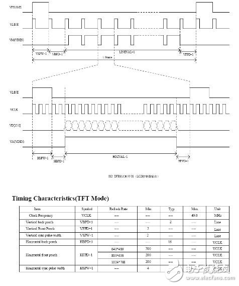
Sijee offers different types of fiber adaptors comply with ITU standard, main products including Fiber Mating Sleeve Adaptor, Fiber Hybrid Adaptor, Fiber Bare Fiber Adaptor, Fiber Mechanical Attenuator, Field Assembly Optical Connector (FAOC), Splice-On Connector, Semi-finished Fiber Connector, etc.
Optical Fiber Couplers,Optical Fiber Adapter,Fiber Optic Adapter,Fiber Optic Flange are available.
Features:
1. Compliant with: IEC, JIS, Telcordia
2. Convenience and ease of handling
3. Optical performance 100% factory tested
4. Flange or threaded mounting type
5. Ceramic/Zirconia or phosphorous bronze sleeves
6. Good changeability and repeatability
Applications:
1. Telecommunication networks
2. FTTX, FTTH
3. LAN, WAN, CATV networks
4. Fiber communications, Data communication networks and processing, Industrial, Mechanical and Military.


Wince code is written to the LCD driver reference, how do digital products are LCD dead pixels?
Is the dead pixel of digital products a dead pixel in the LCD? 1. What is the CCD/LCD dead point? What are the dead pixels and highlights?