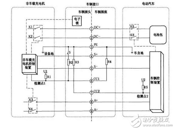
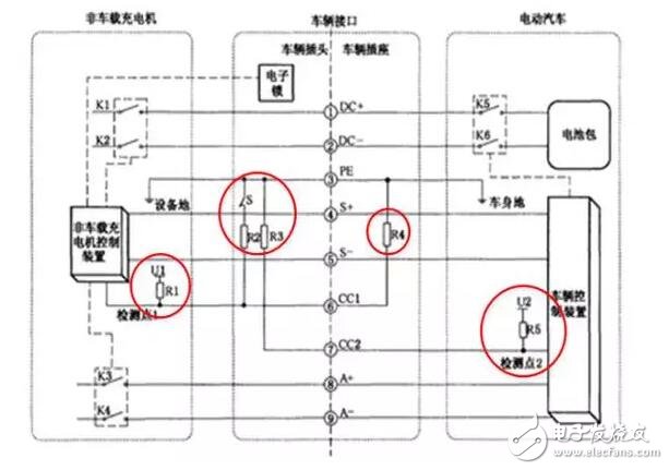
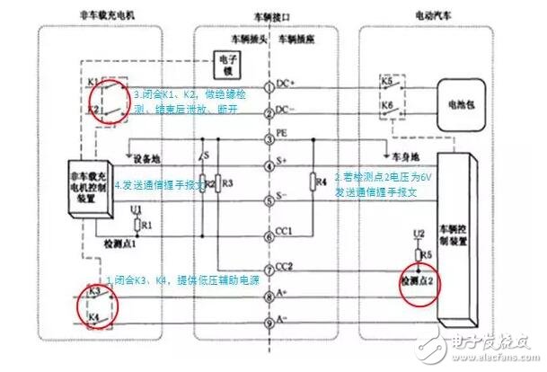
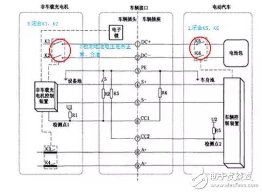
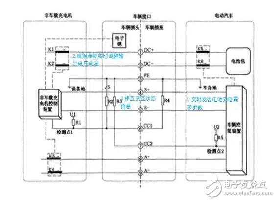
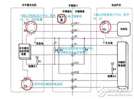
In this document, we will introduce in detail how to charge the DC charging piles for netizens today. Before describing the charging process of DC charging piles, it is necessary to review the contents of the previous article, DC charging line composition. Figure 1 DC charging diagram As shown above, the DC charging pile output consists of 9 lines, which are: DC power line: DC+, DC-; equipment ground: PE; charging communication line: S+, S-; charging connection confirmation line: CC1, CC2; low voltage auxiliary power line: A+, A-. The DC charging pile is used to charge the electric vehicle through these 9 lines. The specific charging model is as follows: Figure 2 DC charging model We can see that the left side is the off-board charger (ie DC charging pile), and the right side is the electric car, which is connected through the vehicle socket. The S switch in Figure 3 is a normally closed switch associated with the button on the DC charging gun head (ie mechanical lock). When we press the button on the charging gun head, the S switch opens. In Figure 3, U1 and U2 are a 12V pull-up voltage, R1~R5 are resistors with a resistance of about 1000 ohms, R1, R2, and R3 are on the charging gun, and R4 and R5 are on the vehicle socket. Figure 3 DC charging model Vehicle interface connection confirmation phase: When we press the gun button, insert it into the vehicle socket and release the gun button. The detection point 1 of the charging post will detect a level change of 12V-6V-4V. Once 4V is detected, the charging post will judge that the charging gun is successfully inserted, the vehicle interface is fully connected, and the electronic lock in the charging gun is locked to prevent the gun head from falling off. DC charging pile self-test stage: After the vehicle interface is fully connected, the charging post will close K3, K4, so that the low-voltage auxiliary power supply circuit is turned on, and the electric vehicle control device is powered (some vehicles do not need to supply power) (after the vehicle is powered, it will be based on the voltage of the monitoring point 2) Determine whether the vehicle interface is connected. If the voltage value is 6V, the vehicle device starts to send a communication handshake message, and then close K1 and K2 to perform insulation detection. The so-called insulation detection, that is, detecting the insulation performance of the DC line, ensures the subsequent charging process. Security. After the insulation detection is completed, the bleeder circuit will be put into the bleeder energy, and K1 and K2 will be disconnected, and the communication handshake message will be sent periodically. Figure 4 Schematic diagram of the self-test phase of the charging pile Charging ready stage: Next, the stage where the electric vehicle and the DC charging pile are mutually arranged, the vehicle control K5 and K6 are closed, the charging circuit is turned on, and the charging pile detects that the battery voltage of the vehicle terminal is normal (the battery voltage error described in the voltage and communication message is ≤± 5%, and within the range of the maximum and minimum voltage of the charging post, K1 and K2 are closed, then the DC charging line is turned on, and the electric car is ready to start charging. Figure 5 Schematic diagram of the charging pile ready stage Charging phase: In the charging phase, the vehicle sends the parameters of the battery charging demand to the charging pile in real time, and the charging pile adjusts the charging voltage and current in real time according to the parameter, and sends each state information (the charging pile output voltage current, the vehicle battery voltage current, the SOC, etc.). ). Figure 6 Schematic diagram of the charging stage of the charging post End of charge phase: The vehicle will judge whether to end the charging according to whether the BMS has reached the full state or the "charging pile stop charging message" sent by the charging pile (the abnormal condition is introduced in the following article). When the above charging end condition is satisfied, the vehicle will send "vehicle stop charging message", and disconnect K5, K6 after confirming that the charging current is less than 5A. When the charging pile reaches the charging end condition set by the operator, or receives the "vehicle stop charging message" sent by the car, it will send "charging pile stop charging message", and control the charging pile to stop charging, confirm the charging current. After less than 5A, disconnect K1 and K2, and put it into the bleeder circuit again, and then disconnect K3 and K4. Figure 7 Schematic diagram of the charging end of the charging pile
Adopting KN95 grade anti-particulate matter filtering technology and antibacterial environmental protection fabnc, effectively filtering and protecting from PM2.5 air particulate matter and bacteria. without breathing valve.
Adopting KN95 grade anti-particulate matter filtering technology and antibacterial environmental protection fabnc, effectively filtering and protecting from PM2.5 air particulate matter and bacteria. without breathing valve. N95 Mask,Surgical Mask,Earloop Face Mask,Disposable Protective Mask Guangzhou HangDeng Tech Co. Ltd , https://www.hangdengtech.com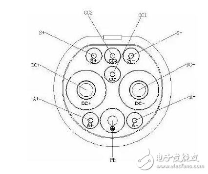
(Details
NIOSH Approved: KN95
FDA Cleared
Helps protect against certain airborne biological particles
Fluid resistant and disposable
Features include:
NIOSH approved KN95
Meets CDC guidelines for Mycobacterium tuberculosis exposure control
99% BFE (Bacterial Filtration Efficiency)
Fluid resistant
Collapse resistant cup shape design
Braided headbands, cushioning nose foam, and light weight construction for comfortable wear)