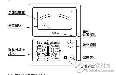
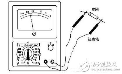
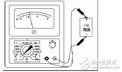
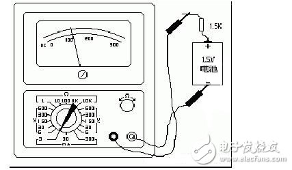
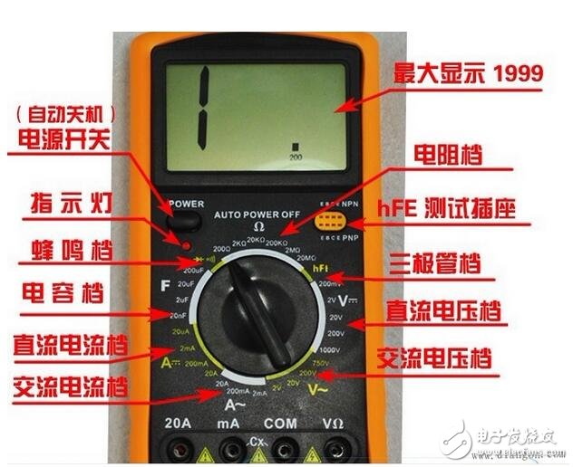
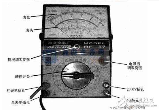
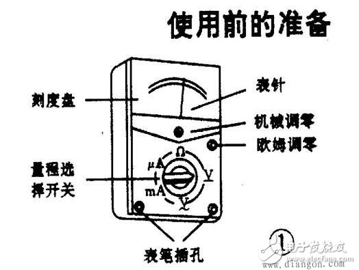
The “multimeter†is the abbreviation of the universal meter, which is an indispensable tool in our electronic production. The multimeter can measure current, voltage, resistance, and some can also measure the amplification of the triode, frequency, capacitance capacity, logic potential, decibel value and so on. There are many types of multimeters, and the most popular ones are mechanical pointers and digital multimeters. They have their own advantages and disadvantages; for electronic beginners, it is recommended to use a pointer multimeter, because it is very helpful for us to familiar with some electronic knowledge principles. The following mainly introduces the measurement principle of the mechanical pointer multimeter. The basic principle of such a multimeter is to use a sensitive magneto-electric DC ammeter (micro-ampere meter) as the head. When a small current passes through the meter, there is a current indication. However, the meter head cannot pass a large current, so it is necessary to shunt or step down some resistors in series with the series head to measure the current, voltage and resistance in the circuit. The following is given separately. 1. Principle of measuring DC current. As shown in Figure 1a, the current range can be extended by shunting an appropriate resistor (called a shunt resistor) in parallel on the meter head. Changing the resistance of the shunt resistor changes the current measurement range. 2. Measure the principle of DC voltage. As shown in Figure 1b, the voltage range can be extended by stepping down a suitable resistor (called a multiplier) on the meter head to step down. Changing the resistance of the multiplying resistor changes the measurement range of the voltage. 3. Measure the principle of AC voltage. As shown in Fig. 1c, since the meter head is a DC meter, when measuring AC, a parallel and string half-wave rectification circuit is required to rectify the AC into DC and then pass through the meter head, so that it can be based on DC power. Size to measure AC voltage. The method of expanding the AC voltage range is similar to the DC voltage range. 4. Measure the resistance principle. As shown in Figure 1d, a suitable resistor is connected in parallel and in series on the meter head, and a battery is connected in series to pass current through the resistor under test. The resistance value can be measured according to the magnitude of the current. Changing the resistance of the shunt resistor changes the range of the resistor. The dial of the multimeter (for example, the 105 type) is shown on the right. The measurement items and measurement ranges are changed by the knob of the changeover switch. The mechanical zero knob is used to keep the pointer at the left zero position at rest. The “Ω†zero adjustment knob is used to measure the resistance so that the pointer is aligned to the right zero position to ensure accurate measurement values. The measuring range of the multimeter is as follows: DC voltage: 5 files - 0-6V; 0-30V; 0-150V; 0-300V; 0-600V. ? AC voltage: 5 files - 0-6V; 0-30V; 0-150V; 0-300V; 0-600V ? DC current: divided into 3 files - 0-3mA; 0-30mA; 0-300mA. ? Resistance: 5 files - R * 1; R * 10; R * 100; R * 1K; R * 10K Measuring resistance: - first short the table rod together, so that the pointer is deflected to the right, then adjust the "Ω" zero adjustment knob so that the pointer just points to 0. Then, the two rods are respectively contacted with the two ends of the measured resistance (or circuit), and the reading of the pointer on the ohmic scale line (the first line) is read, and then the number of the index is multiplied, which is the resistance value of the measured resistance. . For example, the resistance is measured by R*100, and the pointer is at 80, and the measured resistance is 80*100=8K. Since the left side of the “Ω†tick is densely read and difficult to see, the appropriate ohms should be selected for the measurement. Make the pointer in the middle or right of the tick mark so that the readings are clear and accurate. Each time you change gears, you should short-circuit the two bars and re-adjust the pointer to zero to measure. Measure DC voltage:--First estimate the magnitude of the voltage to be measured, then turn the transfer switch to the appropriate V range, connect the positive bar to the "+" terminal of the measured voltage, and the negative bar to the measured voltage "-" terminal. . Then, according to the range number and the number indicated by the pointer on the standard DC symbol "DC-" scale line (second line), the magnitude of the measured voltage is read. If you measure with V300 volts, you can directly read the indication value of 0-300. If you use V30 volts measurement, you only need to remove a "0" from the digit on the scale line 300, which is regarded as 30, and then treat the numbers such as 200 and 100 as 20, 10 and directly read the pointer indication value. For example, the V6 voltage is used to measure the DC voltage, and the pointer is at 15, the measured voltage is 1.5 volts. Measure DC current: -- Estimate the current to be measured first, then turn the switch to the appropriate mA range, and then connect the multimeter in the circuit as shown. At the same time, observe the tick mark marked with the DC symbol "DC". If the current range is selected in the 3 mA range, then the number on the surface tick mark 300 should be removed from the two "0"s, which is regarded as 3, and then 200. 100 is regarded as 2, 1, so that the measured current value can be read. For example, the DC current is measured with a DC 3 mA range, and the pointer is at 100, and the current is 1 mA. Measuring AC voltage: The method of measuring AC voltage is similar to measuring DC voltage. The difference is that there is no positive or negative difference in AC power. Therefore, when measuring AC, the meter bar does not need to be positive or negative. The reading method is the same as the above-mentioned reading of the measured DC voltage, except that the number should be the position of the pointer on the scale line marked with the AC symbol "AC". Third, use the multimeter notes The multimeter is a relatively sophisticated instrument. If it is used improperly, it will not only cause inaccurate measurement but also be easily damaged. However, as long as we master the use of the multimeter and precautions, and be cautious, the multimeter can be durable. The following should be noted when using a multimeter: 1) The measurement current and voltage cannot be misaligned. If the resistance or current is mistakenly measured, the meter will be easily burned out. When the multimeter is not in use, it is best to rotate the gear to the highest level of the AC voltage to avoid damage due to improper use. 2) When measuring DC voltage and DC current, pay attention to the "+" and "-" polarity. Do not connect the wrong one. If you find that the pointer is open and reversed, you should immediately change the watch bar to avoid damaging the pointer and the meter. 3) If you do not know the magnitude of the voltage or current to be measured, you should first use the highest grade, and then select the appropriate gear to test, so as to avoid excessive deflection of the hands and damage the meter. The closer the selected gear is to the measured value, the more accurate the measured value will be. 4) When measuring the resistance, do not touch the naked ends of the components (or the metal parts of the two bars) with your hands to prevent the human body resistance from being connected in parallel with the measured resistance, which makes the measurement results inaccurate. 5) When measuring resistance, if the two rods are shorted, adjust the “Zero Ohm†knob to the maximum, the pointer still can't reach 0. This phenomenon is usually caused by insufficient battery voltage in the watch. It should be replaced with new ones. The battery can be accurately measured. 6) When the multimeter is not in use, do not screw it in the resistance file, because there is a battery inside. If you accidentally make the two watch rods touch and short circuit, it will not only consume the battery, but even damage the meter when it is serious. 1. The multimeter is an indispensable measuring instrument for power electronics and other departments, generally for the purpose of measuring voltage, current and resistance. 2. The multimeter is divided into a pointer multimeter and a digital multimeter according to the display mode. 3. The multimeter can be divided into three types according to the range conversion: manual range (MAN RANGZ), automatic range (AUTO RANGZ), manual range (AUTO/MANRANGZ) 4. According to function, use and price, it can be divided into 9 categories, low, medium and high gear digital multimeters, digital/analog hybrid meters, digital/hybrid dual display instruments, universal oscilloscopes, etc. 1, the choice of pointer table and digital table: 1. The pointer table reading accuracy is poor, but the process of pointer swing is relatively intuitive, and the amplitude of the swing speed can sometimes objectively reflect the measured size (such as measuring the slight difference of the TV data bus (SDL) when transmitting data. Jitter); the digital meter reads intuitively, but the process of digital changes looks messy and not easy to watch. 2. There are generally two batteries in the pointer table, one low voltage 1.5V, one high voltage 9V or 15V, and the black test pen is the positive end relative to the red test pen. Digital watches are often used with a 6V or 9V battery. In the resistance file, the output current of the meter in the pointer table is much larger than that of the digital meter. With the R&TImes; 1 Ω file, the speaker can make a loud “beep†sound, and even the light-emitting diode (LED) can be illuminated with the R&TImes; 10kΩ file. 3. In the voltage file, the internal resistance of the pointer table is relatively small compared to the digital meter, and the measurement accuracy is relatively poor. Some high-voltage micro-currents can't even be measured because their internal resistance will affect the circuit under test (for example, when measuring the accelerating voltage of a TV tube, the measured value will be much lower than the actual value). The internal resistance of the digital meter voltage file is very large, at least in the mega-ohm range, and has little effect on the circuit under test. However, the extremely high output impedance makes it susceptible to induced voltage, and the data measured in some cases where electromagnetic interference is relatively strong may be virtual. 4. In short, the pointer table is used in the analog circuit measurement of relatively high current and high voltage, such as TV set and audio power amplifier. Digital meters, such as BP machines, mobile phones, etc., are used in the measurement of digital circuits with low voltage and low current. Not absolute, the pointer table and the digital table can be selected according to the situation. 2, measurement skills (if not stated, it refers to the pointer table): 1. Measure the speaker, earphone, and dynamic microphone: use R&TImes; 1Ω file, one of the pens is connected to one end, and the other pen touches the other end. When normal, it will emit a crisp sound. If it doesn't ring, the coil is broken. If the sound is small and sharp, there is a problem with the rubbing circle. 2, measuring capacitance: use the resistance file, according to the capacity of the capacitor to select the appropriate range, and pay attention to the measurement of the electrolytic capacitor black pen to the capacitor positive. 1. Estimate the size of the microwave-level capacitor capacity: It can be judged according to the maximum amplitude of the pointer swing by experience or by referring to the standard capacitance of the same capacity. The capacitors to be referenced do not have to have the same withstand voltage values, as long as the capacities are the same. For example, it is estimated that a 100μF/250V capacitor can be referenced by a 100μF/25V capacitor, and as long as their pointer swings to the same maximum amplitude, the capacity can be determined. 2. Estimate the size of the skin-level capacitor: use R&TImes; 10kΩ, but only 1000pF or more. For a 1000pF or slightly larger capacitor, as long as the hands are slightly swung, the capacity is considered sufficient. 3. Measure whether the capacitor leaks: For a capacitor of more than one thousand microfarads, it can be quickly charged with R×10Ω file, and the capacitance capacity is initially estimated, then changed to R×1kΩ file and continue to measure for a while, then the pointer is not It should be returned, but should be parked at or very close to the place, otherwise there will be leakage. For some timing or oscillating capacitors below tens of microfarads (such as the oscillating capacitor of color TV switching power supply), the leakage characteristics are very high, as long as there is a slight leakage, it can not be used. At this time, after the R×1kΩ gear is charged, Then continue to use R × 10kΩ file to continue measurement, the same needle should stop at the ∞ and should not return. 3. On-line detection of diodes, triodes, and voltage regulators is good or bad: because in the actual circuit, the bias resistance of the triode or the peripheral resistance of the diode and the voltage regulator are generally large, mostly in the hundreds of thousands of ohms or more. We can use the multimeter's R × 10 Ω or R × 1 Ω file to measure the PN junction in the road. When measuring the road, the PN junction measured by R×10Ω should have obvious positive and negative characteristics (if the difference between the forward and reverse resistance is not obvious, it can be measured by R×1Ω), and the general forward resistance is in R. When the ×10Ω is measured, the hands should be indicated at about 200Ω. When the R×1Ω is measured, the hands should be indicated at 30Ω (may vary slightly depending on the phenotype). If the measured value of the forward resistance is too large or the reverse resistance is too small, it indicates that there is a problem with this PN junction, and this tube is also problematic. This method is particularly effective for maintenance, can find the bad tube very quickly, and even measure the tube that has not completely broken but the characteristics are deteriorated. For example, when you measure a PN junction with a small resistance value, the forward resistance is too large. If you solder it down and use the commonly used R×1kΩ file, it may still be normal. In fact, the characteristics of this tube have deteriorated. Not working or unstable. 4. Measuring resistance: It is important to select the range. When the pointer indicates 1/3~2/3 full scale, the measurement accuracy is the highest and the reading is the most accurate. It should be noted that when measuring the large resistance value of the ohms level with the R×10k resistance file, the fingers should not be pinched at both ends of the resistor, so that the human body resistance will make the measurement result smaller. 5. Measure the Zener diode: The voltage regulator of the regulator tube we usually use is generally greater than 1.5V, and the resistor file below R×1k of the pointer meter is powered by the 1.5V battery in the meter. The resistance voltage measuring tube below R×1k is like a measuring diode, and has complete unidirectional conductivity. However, the R×10k file of the pointer table is powered by a 9V or 15V battery. When the voltage regulator with a voltage regulation value less than 9V or 15V is measured with R×10k, the reverse resistance value will not be awkward, but there is a certain Resistance, but this resistance is still much higher than the forward resistance of the Zener. In this way, we can initially estimate the quality of the Zener tube. However, a good voltage regulator tube must have an accurate voltage regulation value. How can this voltage regulator value be estimated under amateur conditions? It's not difficult, just go find a pointer table and you're done. The method is: first place a watch in the R×10k file, and the black and red test pens are respectively connected to the cathode and the anode of the Zener tube, at this time, the actual working state of the Zener tube is simulated, and another table is placed. The voltage file V×10V or V×50V (according to the voltage regulation value), the red and black test pens are respectively connected to the black and red test pens of the watch, and the measured voltage value is basically this. The voltage regulation value of the Zener diode. Say "basically" because the bias current of the first watch to the Zener diode is slightly smaller than the bias current during normal use, so the measured voltage will be slightly larger, but the difference is not much difference. . This method can only estimate the voltage regulator whose voltage regulation value is lower than the voltage of the high voltage battery of the pointer meter. If the voltage regulator voltage is too high, it can only be measured by the external power supply. (It seems that when we use the pointer meter, the high voltage battery voltage is 15V, which is more suitable than 9V.) 6. Measuring triode: Usually we need to use R×1kΩ file, whether it is NPN tube or PNP tube, no matter it is low power, medium power, high power tube, it should be the same as the diode. Electrical, the reverse resistance is infinite, and its forward resistance is about 10K. In order to further estimate the quality of the pipe, if necessary, the resistance gear position should be changed for multiple measurements. The method is: set R × 10 Ω to measure the PN junction forward conduction resistance is about 200 Ω; set R × 1 Ω The positive conduction resistance of the PN junction is about 30Ω. (The above is the data measured by the 47-type meter. The other models have different outlines. You can test a few good tubes and sum up them.) If the reading is too large. Too much, it can be concluded that the characteristics of the pipe are not good. The table can also be placed in R × 10kΩ and then tested, the tube with low withstand voltage (the voltage of the triode is above 30V), the reverse resistance of the cb junction should also be in the ∞, but the reverse resistance of the be junction There may be some, the hands will be slightly deflected (generally not more than 1/3 of the full scale, depending on the pressure resistance of the pipe). Similarly, when measuring the resistance between ec (for NPN tubes) or between ce (for PNP tubes) with R × 10 kΩ, the hands may be slightly deflected, but this does not mean that the tubes are bad. However, when measuring the resistance between ce or ec with R × 1kΩ or less, the indication of the meter should be infinite, otherwise the tube is problematic. It should be noted that the above measurements are for silicon tubes and not for tubes. But now the fistula is rarely seen. In addition, the "reverse" is actually different for the PN junction and the direction of the NPN tube and the PNP tube. The first method: For the pointer meter with the triode hFE jack, after measuring the b pole, insert the triode into the jack at random (of course, the b pole can be inserted accurately), measure the hFE value, and then The tube was inverted and measured again. The hFE value was measured once and the position of each pin was inserted correctly. The second method: for the table without the hFE measuring jack, or the tube is too large to be inserted into the jack, you can use this method: For the NPN tube, first measure the b pole (the tube is NPN or PNP and its b foot) It's easy to measure, isn't it?), put the watch in the R×1kΩ file, and connect the red pen to the hypothetical e-pole (note that the hand holding the red pen does not touch the pen tip or pin), the black pen is connected to the hypothetical c pole, while pinching the tip of the meter and the pin with your fingers, take the tube up, use your tongue to rub the b pole, see the pointer should have a certain deflection, if your pens are connected correctly, the pointer will deflect Larger, if the connection is not correct, the pointer deflection will be smaller, the difference is obvious. From this, the c and e poles of the tube can be determined. For the PNP tube, the black meter should be connected to the hypothetical e-pole (the hand should not touch the nib or the pin), the red meter pen should be connected to the hypothetical c-pole, and the finger tip and the pin should be pinched with the fingers, and then the tongue tip is used to b) Extremely, if the pens are connected correctly, the head pointer will be deflected relatively large. Of course, the meter should be exchanged twice during the measurement, and the final reading can be made after comparing the readings. This method is suitable for all shapes of triodes, which is convenient and practical. Depending on the deflection of the hands, it is also possible to estimate the magnification of the tube, which is of course empirical. The third method: first determine the NPN or PNP type of the tube and its b pole, then place the meter in the R×10kΩ file. For the NPN tube, the black meter pen is connected to the e pole, and the red meter pen is connected to the c pole, the needle may have a certain amount. Deflection, for the PNP tube, the black meter pen is connected to the c pole, and the red meter pen is connected to the e pole, the needle may have a certain deflection, and vice versa. This makes it possible to determine the c and e poles of the triode. However, for high pressure pipes, this method is not applicable. For the common imported high-power plastic tube, the c-pole is basically in the middle. The b poles of the medium and small power tubes may be in the middle. For example, the commonly used 9014 triode and other series of triodes, 2SC1815, 2N5401, 2N5551 and other triodes, the b pole is in the middle. Of course, they also have c in the middle. Therefore, when repairing and replacing the triode, especially these low-power triodes, if they are not used, they should be installed directly as they are, and must be measured first. Â
52 Jack,Professional Plastic 6p6c RJ45 ModularJack manufacturer is located in China, including Top Entry Rj45,6p6c Modular Connectors,RJ45 Connector Diagram, etc.
The RJ-45 interface can be used to connect the RJ-45 connector. It is suitable for the network constructed by twisted pair. This port is the most common port, which is generally provided by Ethernet hub. The number of hubs we usually talk about is the number of RJ-45 ports. The RJ-45 port of the hub can be directly connected to terminal devices such as computers and network printers, and can also be connected with other hub equipment and routers such as switches and hubs.
Plastic 6p6c RJ45 ModularJack,Top Entry Rj45,6p6c Modular Connectors,RJ45 Connector Diagram ShenZhen Antenk Electronics Co,Ltd , https://www.antenkconn.com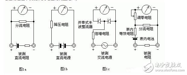

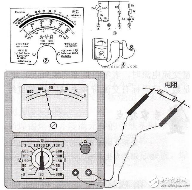
Common models of multimeters, how to use multimeters, diagram of working principle of multimeters
How the multimeter works