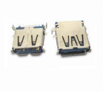
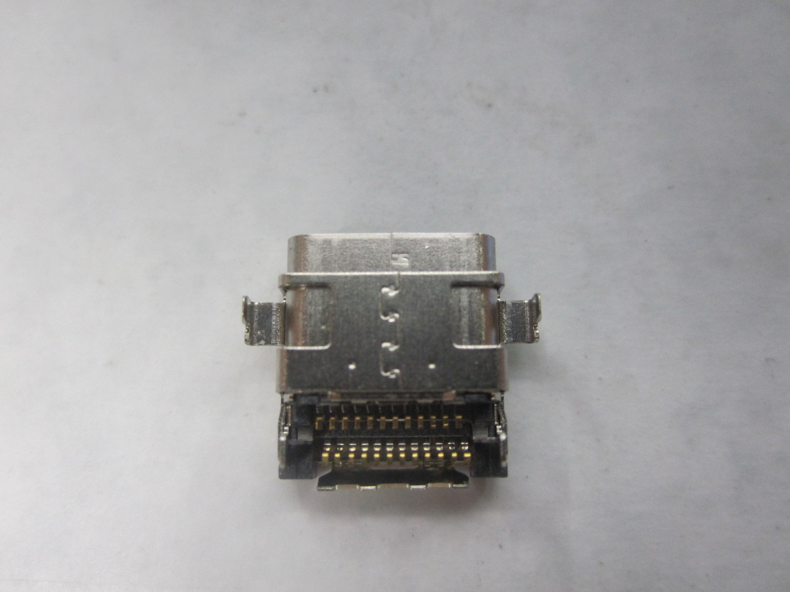
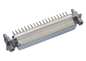
Rectangular I/O Connectors
Antenk develop and specify high-performance I/O's throughout a wide variety of industries. These include SAS, SATA, PCIe, HSSG, FIBRE CHANNEL, INFINIBAND, IEC, CEA, IEEE, VESA, USB and many more.
I/O Connectors Application
Antenk can deliver standard and custom options of the following I/O connectors:
I/O Connectors General Specifications
ELECTRICAL CHARACTERISTICS
Rectangular Connector,Rectangular I Connectors,Rectangular O Connectors,Male Connector Rectangular,I/O Connectors,Input/Output Connectors ShenZhen Antenk Electronics Co,Ltd , https://www.antenk.com
Antenk offers an expansive product line of I/O connectors including USB, HDMI, D-Sub, Modular Jacks, SFP, QSFP+, CXP, iPass+, iPass+ HD and more. In addition to standard I/O connectors and matching cable assemblies.Except a comprehensive range of standard Input/Output connector solutions for high-speed electronic data communication, Antenk engineers can design customized solutions. This extensive selection of I/O connectors and matching cable assemblies includes numerous next-generation solutions.All of our I/O connectors feature a variety of orientation options, as well as PCB and cable mount offerings.
Consumer / PC Products
Networking / Telecommunications Products
Mobile Products
Industrial Products
1394 Connector
Centronic Connector
D-Sub Connector
DVI Connector
Display Port Connector
HDMI Connector
Half Pitch SCSI Connectors
USB Connector
V.35 Connector
OBD Connector


Contact Current Rating:5Amperes.
Dielectric Withstanding.
Dielectric Withstanding Voltage:AC 1000Vr.m.s.
Insulation Resistance:500 Megohms Minimum at DC500V.
Contact Resistance:25 Milliohms Maximum.
Operating Temperature:-55℃~105℃.

MATERIALS:
Contacts:Brass.
Insulator:PBT,UL94V-O Rated.
Shell:Cold Rolle Steel.
Metal Watertight Frame:PBT,UL94V-0.
O-Ring:Silicone.
NOTE:
Position:09PIN,15PIN,25PIN,37PIN.
Wireless communication design using MATLAB
The wireless engineering team leverages the latest MATLAB® to streamline and accelerate development cycles, from system-level simulation down to hardware implementation. By using MATLAB, engineers can significantly cut time and simplify complex processes in several key ways:
- **Verify algorithm concepts** through simulation and over-the-air testing
- **Explore and optimize system behavior** using a wide range of models, including digital, RF, and antenna components
- **Move to implementation** after identifying and resolving design issues
- **Streamline testing and verification** with MATLAB and Simulink test tools
- **Automate HDL or C code generation** for prototyping and deployment
- **Reuse models** across projects to speed up iterations and support next-generation developments
According to the team, this approach led to a 30% reduction in overall development time, an 85% decrease in functional verification time, and a significant drop in redesign efforts. They were able to implement FPGAs and ASICs on the first try without defects.
MATLAB is widely used in wireless communication design, offering powerful tools for developing advanced technologies like 5G and beyond. It supports end-to-end design approaches covering baseband, RF systems, and hardware. Key features include:
- **Algorithm libraries, reference models, and measurement tools** for simulating and analyzing cutting-edge technologies such as modulation techniques, massive MIMO, and mmWave transmission
- A **flexible antenna array design tool** for modeling phased arrays and evaluating beamforming algorithms
- The ability to **benchmark real-world performance** using SDR platforms or custom FPGA hardware for rapid prototyping and testing
With MATLAB and Simulink, engineers can optimize system performance and identify potential issues before moving to hardware, ensuring a more efficient and reliable development process.
For LTE and WLAN emulation and testing, MATLAB provides robust support for physical layer (PHY) development, gold reference verification, and compliance testing. It allows users to generate and analyze waveforms, automate test bench creation, and easily customize designs for simulation and over-the-air testing.
Key features for LTE and WLAN development include:
- Simulation and design verification for LTE, LTE-A, and 802.11 standards
- Real-time waveform transmission and reception using SDR hardware and RF instruments
- Carrier aggregation, beamforming, and antenna array modeling for MIMO systems
- Signal analysis and parameter recovery
- RF system and antenna array modeling
MATLAB and Simulink also enable the modeling of digitally controlled RF front ends and antenna arrays, making it easier to explore different scenarios and optimize signal chain performance—even for those without deep RF expertise.
By integrating RF architecture modeling with measured characteristics, engineers can simplify the integration of RF front ends into larger systems. Fast simulation-based modeling of RF transceivers helps speed up the design process, while MATLAB algorithms like DPD and AGC can mitigate power amplifier distortion and interference.
Additionally, MATLAB allows for the simulation of antenna effects on RF front-end design and supports digital and hybrid beamforming for phased array antennas.
Connecting MATLAB and Simulink to SDR hardware enables real-time airborne transmission testing of wireless designs, whether in the office, lab, or field. This capability allows engineers to send and receive standard-compatible and custom waveforms, verify designs with real signals, and analyze captured data using built-in tools.
Finally, MATLAB and Simulink facilitate SDR prototyping and implementation by automating HDL and C code generation, reducing manual errors and accelerating hardware development on various platforms. This includes fixed-point model design, target-optimized code generation, and FPGA-in-loop testing for validation.