Yonghao Wire Company is committed to providing high quality electrical products, taking YC02 photovoltaic cable connectors as an example, whose superior performance makes them a reliable choice. We meet our customers' needs with innovative technology and superior quality, providing reliable power connectivity solutions for the renewable energy industry.
Applicable scenarios include photovoltaic power plants, solar power generation systems, outdoor photovoltaic equipment, etc., to provide reliable electrical connections for these environments to ensure the efficient operation of solar power generation systems.
YC02 photovoltaic cable connector has the following advantages: solar connect, cable connector, connector terminal,pv connector, dc solar cable connector Suzhou Yonghao Cable Co.,Ltd. , https://www.yonghaocable.com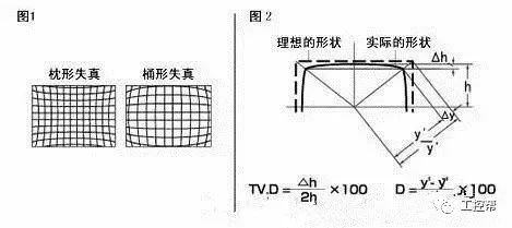
High reliability: The YC02 connector design is carefully optimized to ensure a stable and reliable electrical connection in the photovoltaic system, reducing the failure rate.
Strong water resistance: with excellent waterproof performance, adapt to outdoor, bad weather and other complex environments, to ensure long-term stable operation of the connector.
Corrosion resistance: Strong corrosion resistance, can maintain the stability of the connector in harsh weather conditions, extend the service life.
Anti-ultraviolet: It has anti-ultraviolet characteristics and is suitable for outdoor photovoltaic power plants and other scenes that need to be exposed to sunlight for a long time.
High temperature resistance: YC02 connectors maintain stable performance in high temperature environments and are suitable for devices such as photovoltaic battery modules and inverters.
Applicable scenarios include photovoltaic power plants, solar power generation systems, outdoor photovoltaic equipment, etc., to provide reliable electrical connections for these environments to ensure the efficient operation of solar power generation systems.
Detailed description of twenty-three related terminology for machine vision industrial lenses
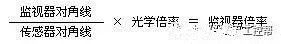
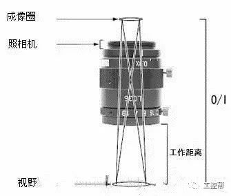
In a machine vision system, the lens plays a role similar to that of the human eye, as it is responsible for focusing the optical image of the target onto the photosensitive surface of the image sensor (camera). All image data processed by the vision system originates from the lens, and its quality directly impacts the overall performance of the system. Below is a detailed explanation of key technical terms related to industrial lenses used in machine vision.
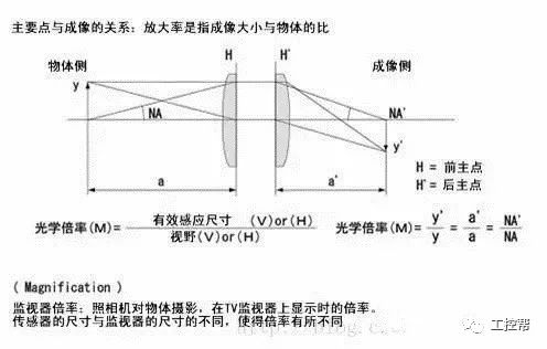
First, **distortion** refers to the deviation of the image shape from the original object. It can be categorized into pincushion distortion and barrel distortion, as shown in the image below: