Thin Wafers,Silicon Wafers,Glass Wafers,4 Inch Wafers Zoolied Inc. , https://www.zoolied.com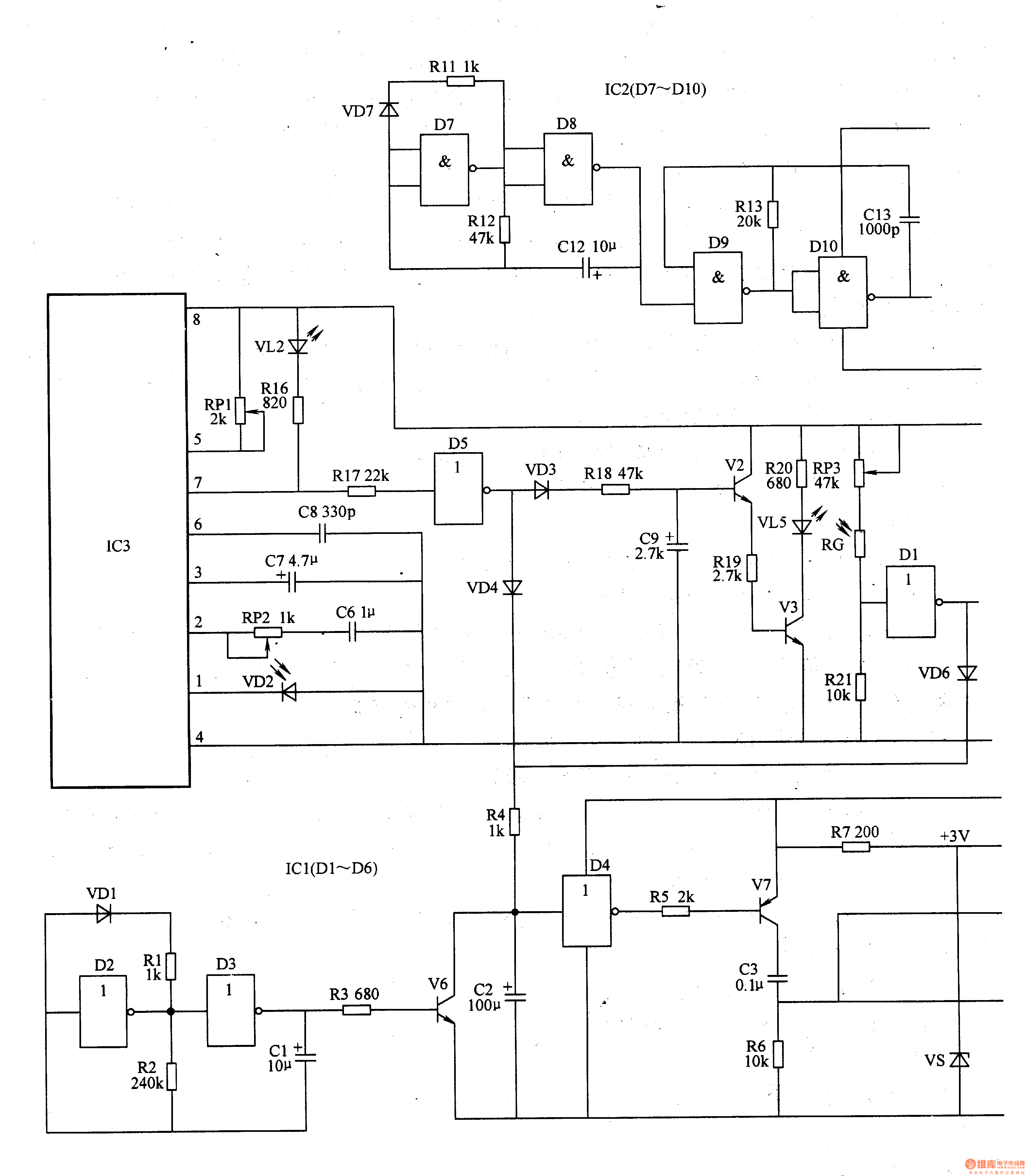
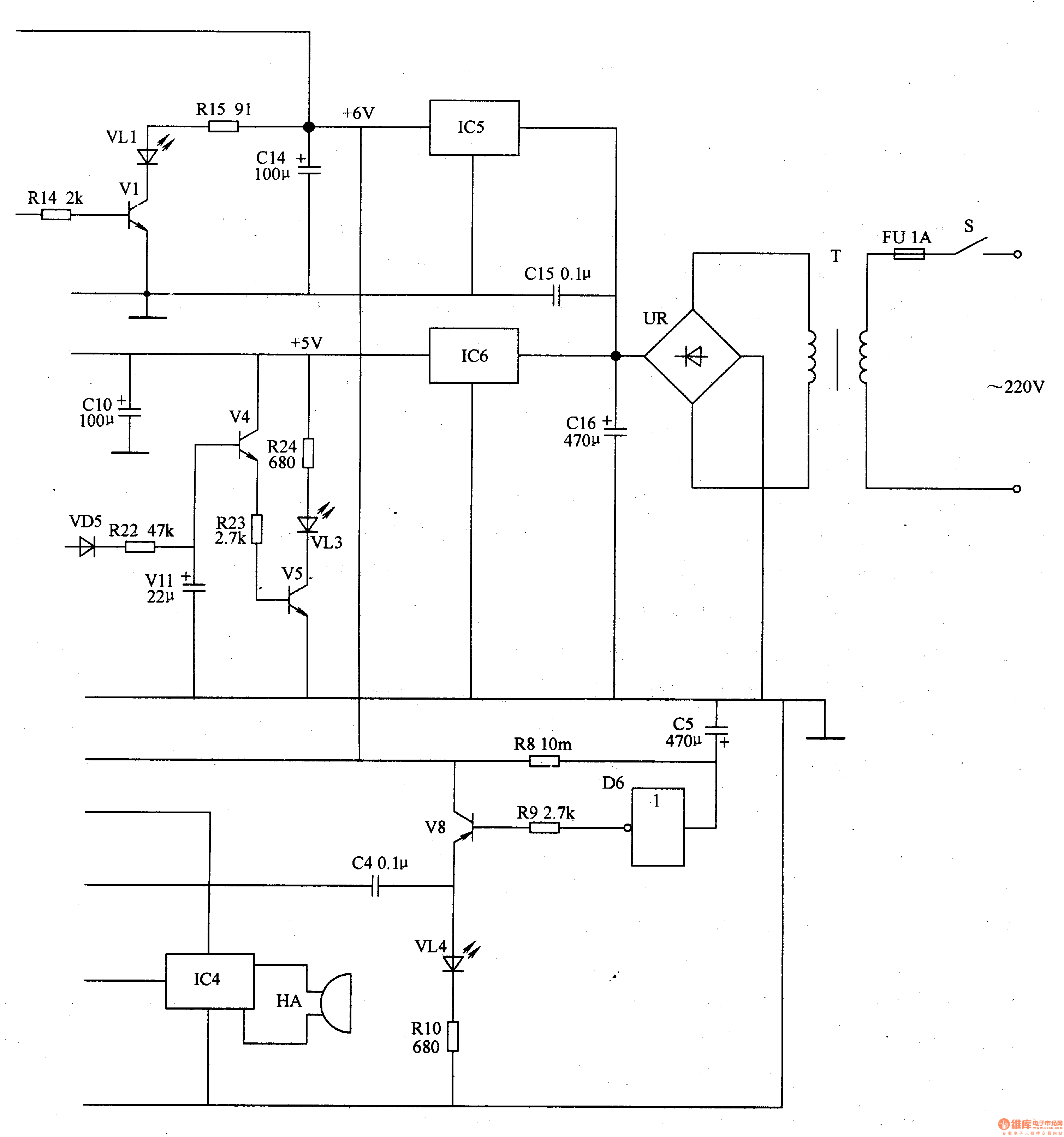
The power circuit is composed of a power switch S, a fuse FU, a power transformer T, a rectifier bridge stack UR, a filter capacitor C10, a Cl4-C16, and a three-terminal voltage regulator integrated circuit IC5, 1C6.
The infrared transmitting circuit is composed of a resistor R11-Rl5, a capacitor Cl2, a C13, a diode VD7, a NAND gate integrated circuit IC2 (D7-D1O), a transistor V1 and an infrared light emitting diode VLl.
The infrared receiving control circuit is composed of infrared photodiode VD2, resistor R16-R18, potentiometer RPl, RP2, capacitor C6-C8, light emitting diode VL2, D5 inside the non-gate integrated circuit lCl (D1-D6) and diode VD3, VD4. .
The photometric routing photoresistor RG, the resistors R2l, R22, the diode VD5, the potentiometer RP3 and the non-gate D1 inside the lCl are composed.
The clear pulse circuit is composed of a diode VD1, a capacitor C1, a resistor Rl-R3, and a non-"D2, D3 and a transistor V6 inside the IC1.
The timing control circuit is composed of a capacitor C5, resistors R8, R9, a NOT gate D6, and a transistor V8.
Sound and light alarm circuit consists of transistors V2-V5, V7, V8, resistors R5-R7, RlO, Rl9, R2O, R23, R24, LED VL3-VL5, Zener diode VS, music integrated circuit lC4 and buzzer HA composition.
Turn on the power switch S, the AC 220V voltage is divided into two by the T step-down, UR rectification and C16 filtering to generate 9V DC voltage: one way is regulated by IC5 to +6V, as the working voltage of the infrared transmitting circuit and ICl; the other way The voltage is regulated to +5V by lC6, and is supplied to the infrared receiving circuit, the flashing alarm circuit and the metering circuit. The +6V voltage is also regulated by R7 and VS regulated to provide +3V operating voltage for IC4.
After the whole circuit of the whole machine is energized, the ultra-low frequency oscillator composed of NAND gates D7, D8 and VD7, R11, Rl2, Cl2 oscillates to generate lHz pulse signal to l5kHz oscillator (by NAND gate Dg, DlO and resistor The device R13 and the capacitor Cl3 are configured to be modulated, and after the modulation, the pulse signal is amplified by V1, and then the VL1 is driven to emit the modulated infrared light.
When the distance between the user's head and the writing surface is greater than 35 cm, the VD2 does not receive the infrared light emitted by the VL, and the 7-pin of the IC3 outputs a high level. When the distance between the user's head and the writing surface is less than 35 cm, VD2 receives the infrared light emitted by VL1 (infrared light reflected from the head) and converts it into an electrical signal, which is processed internally by IC3. 7 feet output low level, make VL2 light; at the same time, non-gate D5 outputs high level, VD3 and VD4 turn on, V light is lit, non-gate D4 output low level, V7 saturation is turned on, IC4 is triggered to work, The HA beeps to alert the user to the read and write distance.
When the timing time has not expired, the NOT gate D6 outputs a high level, V8 is in an off state, and the VM does not emit light. When the timing time is over, the non-gate D6 outputs a low level, which makes V8 turn on, VL4 lights up, and the high level of the V8 collector output triggers lC4 through C4, so that IC4 works, HA emits a beep, reminds the use The person should take a break.
When the ambient light is suitable for reading and writing requirements, the resistance of RG is small, the non-gate D1 outputs a low level, VD5, VD6, V4 and V5 are all in an off state, and VL3 does not emit light. If the ambient light is lower than the read/write requirement, the resistance of RG becomes larger, the non-gate D1 outputs a high level, VD5, VD6, V4 and V5 are both turned on, VL3 is lit; at the same time, the non-gate D4 outputs a low level, V7 Turned on, IC4 is triggered to work. The HA beeps to alert the user to weak ambient light.
In order to prevent the erroneous triggering of the audible alarm circuit when the user accidentally bows or blocks the light, the oscillator composed of the non-gates D2, D3 and VDl, Rl, R2, and Cl outputs one pulse every 5s, then the V6 is turned on, C2 Discharge through V6. Thus, the alarm circuit operates only when the user's read/write distance is low for more than 5 seconds.
Adjusting the resistance of RPl and RP2 can change the sensitivity of infrared control.
Adjusting the resistance of RP3 can change the sensitivity of the metering circuit.
Component selection
Rl-R24 uses 1/4W metal film resistor or carbon film resistor.
RPl-RP3 uses a miniature synthetic carbon film potentiometer or variable resistor.
Cl, C2, C5, C7, C9, ClO-Cl2, C14 and C16 are all aluminum electrolytic capacitors with a withstand voltage of 16V; C3, C4, C6 and Cl5 are all monolithic or polyester capacitors; C8 and C13 are high. Frequency ceramic capacitor or glass glaze capacitor.
VDl and VD3-VD7 select 1N4148 type silicon switch diode for use; VD2 selects type SE302 type infrared photodiode.
VLl selects PH303 type infrared light-emitting diode; VL2-VL5 selects high-brightness light-emitting diode of φ3mm.
VS selects 1/2W, 3V silicon Zener diode.
UR selects the rectifier bridge stack of lA and 5OV.
Vl-V6 selects S9013 or 3DG9013 silicon NPN transistor for use; V7 and V8 select S8550 or C9550, 3CG8550 silicon PNP transistor.
lCl selects CD4069 type six non-gate integrated circuit; IC2 selects CD4011 type four NAND gate integrated circuit; IC3 selects CXD2O106 type infrared signal processing integrated circuit; IC4 selects KD9300 type music integrated circuit; lC5 selects LM7806 type three end steady voltage integrated circuit; IC6 selects LM7805 type three-terminal regulator integrated circuit.
T selects 3-5W, the secondary voltage is 9V power transformer.
HA uses a piezoelectric buzzer.
S selects 5A, 220V power switch.