OTL is the abbreviation of English Output Transformer Less Amplifier, which is a power amplifier without output transformer. This article refers to the address: http:// one. OTL tube power amplifier circuit features
The output load of a common tube power amplifier is a moving coil type speaker, and its impedance is very low, only 4 to 16 Ω. The internal resistance of the general power amplifier tube is relatively high. In the ordinary push-pull power amplifier, the load impedance of the screen to the screen is generally 5 to 10 kΩ, so the low-impedance speaker cannot be directly driven, and the output transformer must be used for impedance transformation. Since the output transformer is an inductive component, the impedance of the inductor is different due to the different signal frequencies of the transformer. In order to extend the low-frequency response, the inductance of the coil should be large enough, and the number of turns is increased, so the distributed capacitance between each layer is correspondingly increased, which limits the high-frequency expansion, and also causes nonlinear distortion and phase. distortion.
In order to eliminate these adverse effects, various forms of tube OTL no-output transformer power amplifiers have emerged, and many new power tubes for OTL power amplifiers have been continuously designed and manufactured abroad. The sound quality of the tube OTL power amplifier is clear and transparent, with high fidelity and wide frequency response. The frequency range of the high frequency band and the low frequency band is generally 10HZ ~ 100kHz, and its technical performance such as phase distortion, nonlinear distortion and transient response are all There is a significant improvement.
Two tube OTL power amplifier circuit form
Figure 1 (a) ~ Figure 1 (f) is the basic circuit of the OTL no-output power amplifier. Figure 1 (a) and Figure 1 (b) show the two power supply structure of the OTL power amplifier, namely positive and negative dual power supply and single power supply. In a positive and negative dual-supply OTL power amplifier, the center is the ground potential. This ensures the symmetry of the push-pull circuit, so the output capacitor can be omitted, making the frequency response of the amplifier better. In order to have the same operating voltage for the two push-pull tubes, the single-supply OTL circuit must have the operating voltage at the center point equal to half the supply voltage. At the same time, the capacity of its output capacitor C1 must be large enough to not affect the output impedance and low frequency response requirements. 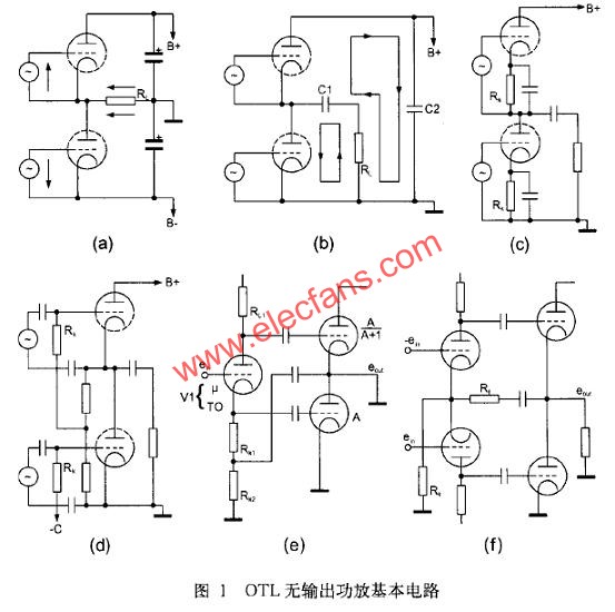
Figure 1 (c) and Figure 1 (d) show the gate bias of the OTL power amplifier tube. Since the cathode of the upper tube is not grounded, the push signal of the upper tube is added between the gate and the cathode, and the push signal of the lower tube can be added between the gate and the ground. As for the biasing mode, the upper tube can be taken out by the center point to the ground, and the bias voltage of the lower tube must be supplied with a special negative voltage source.
Figure 1 (e) and Figure 1 (f) are the application of the OTL inverter circuit. Figure 1(e) shows the excitation of the OTL power amplifier using a screen-shaping inverted inverter circuit. As long as the screen load resistance RL of the inverter tube is equal to the resistance of the cathode load resistor RK, the output excitation voltage is always balanced.
Figure 1 (f) shows the use of a common cathode differential inverter circuit. Since the common cathode resistance RK has a large resistance value and has a deep negative feedback effect, the circuit is stable and reliable. At the same time, as long as the screen load resistances of the upper and lower tubes which are differentially amplified are equal, the screens of the two tubes can always output a pair of push signal voltages of opposite phase and equal amplitude.
Third, the selection of OTL power amplifier circuit
For the output stage of the tube OTL power amplifier, not all power tubes can be applied. It is necessary to select a power tube that meets the following conditions to achieve good results.
1. Low internal resistance characteristics The general internal resistance of the power tube is about 10kΩ, which is not suitable for OTL power amplifiers. The OTL power amplifier must use a power tube with a screen internal resistance of 200 to 800 Ω. These low internal resistance power tubes are available in 6AS7, 6N5P, 6C33C-B, 6080, 6336, and the like.
2. Low screen voltage, high current characteristics Generally, the screen voltage of the power tube is about 400V, the high screen voltage tube can reach 800~1000V, and the OTL power amplifier must use the low screen voltage and high current with the screen voltage between 150~250V. Features a power tube to serve. The low internal resistance power tubes listed above all have low screen voltage and high current operating characteristics. In addition, there are 6C19, 6KD6, 421A, 6146 and other power tubes. These tubes have low screen voltage and high current characteristics, but their screen internal resistance is slightly higher. They should be connected in multiple tubes to be suitable for OTL power amplifiers.
3. Specialized power tubes for new OTL power amplifiers These tubes not only have low internal resistance, but also have low screen voltage and high current characteristics, such as 6HB5, 6LF6, 17KV6, 26LW6, 30KD6, 40KG6, etc. In order to reduce the power consumption of the tube filament, many of the power tubes for the OTL power amplifier have a filament voltage of 20 to 40 V, which is convenient for use in series.
Four kinds of typical circuits of OTL power amplifier
1. New three-pole power tube OTL power amplifier Figure 2 is a 6C33 CB dual triode OTL power amplifier circuit diagram. This circuit adopts foreign new low internal resistance and high power double triode 6C33C-B as OTL power amplifier. Each channel uses a pair of 6C33C-B for power amplification. When outputting 8Ω load, the output power of each channel can reach 40W. 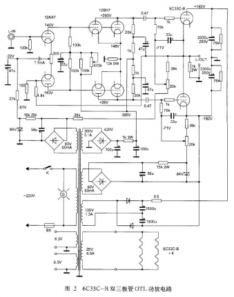
The input stage of the OTL power amplifier adopts a high-amplification double-pole electronic tube 12AX7 to form a pre-stage differential and inverter circuit. The circuit features high input impedance and large dynamic range. In order to widen the frequency response and reduce the phase distortion, a direct coupling between the input stage and the push stage is adopted. In order to improve the gain of the front stage, a voltage of -22 V is applied to the cathode of the differential input tube 12AX7, and a 1.1 mA constant current diode is connected in series to make the front stage work more stable and reliable.
The driving amplifier is driven by a double-triode tube 12BH7 with a medium amplification factor, and the characteristics of the tube are similar to those of the double triodes such as l2AU7, 12JD8, and 5687. In order to increase the screen current and improve the output capability of the push stage, two triodes are used in parallel, and the screen voltage of each tube is as high as 265V, which constitutes a common cathode to drive the amplifying circuit. In order to improve the electrical performance of the push level, reduce the distortion, and widen the frequency response, a deep current negative feedback is added to the cathode of the two tubes.
The OTL amplifier output stage uses a pair of new dual three-pole power tubes 6C33C-B for each channel. A pair of equal-amplitude, opposite-phase push signals are coupled to the power amplifier tube through two 0.47 F capacitors.
The OTL power amplifier stage adopts positive and negative dual power supply forms, and its power amplifier stage operating voltage is ±182V. The highest negative voltage between the gate and cathode of the power amplifier tube 6C33C-B is -60V, the gate negative voltage of the upper tube is supplied by a separate negative voltage source, and the gate negative voltage of the lower tube is supplied by another set of negative voltages.
In order to improve the electrical performance of the OTL power amplifier, an appropriate voltage negative feedback is added between the output terminal and the input terminal of the OTL through a 1.8kΩ resistor, so that the overall electromechanical performance is stable and reliable. The frequency response of this unit is 10 Hz to 200 kHz (±0.1 dB).
In the power supply of the OTL power amplifier, the positive and negative high voltage of the power amplifier stage is obtained by the positive and negative rectification and filtering of the 135V/1.3A winding in the power transformer to obtain a high voltage of ±182V. The screen high voltage of the input stage and the push stage is diode-bridge rectified and filtered by the power transformer 300V/0.1A winding, and the output is +395V high voltage, and is depressurized by the decoupling resistor to obtain +265V and +140V voltages, which are respectively supplied to 12AX7 and 12BH7. . The gate negative voltage power supply is divided into two groups. The two independent windings of the power transformer are rectified and filtered, and then respectively supplied to the gate of the OTL power amplifier tube as a gate negative bias voltage, and through two 20kΩ variable potentiometers. adjust. The filament power supply is divided into 3 groups, and the front channel is 2 groups. The 6C33C-B filament of the power amplifier tube has two usages, which is 12.6V/3.3A when used in series and 6.3V/6.6A when used in parallel. The machine adopts series connection.
2. Ordinary Transistor OTL Power Amplifier Figure 3 is a 6KD6 pentode OTL power amplifier circuit diagram. It is an OTL power amplifier that changes the ordinary beam-emitting quadrupole or five-pole power tube to a triode tube connection, and utilizes the characteristics that the electron tube curtain gate can output a large current under the same gate voltage. Originally, due to the relatively large internal resistance of the screen, the operating current was limited. However, after changing to the triode connection method, the voltage of the screen grid was at the same potential as the screen voltage, and the internal resistance of the screen was greatly reduced, which strengthened the screen. The ability to handle large currents allows for higher power output at low impedance loads. 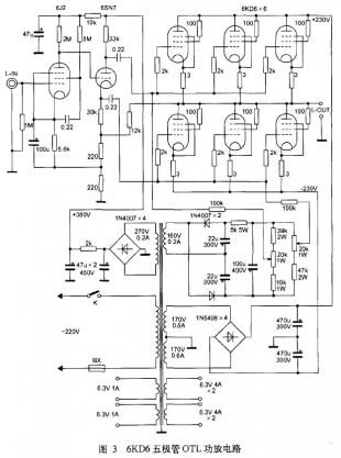
For an OTL power amplifier with a common power tube changed to a triode connection, not all power tubes can be used. It is necessary to use a beam quadrupole or a five-pole power tube with a large screen voltage range, such as 6KD6, 6L6, and 6P3P. , 6146, etc. At the same time, the power amplifier stage must also use multiple power tubes in parallel. In the 8Ω low-impedance load, each channel uses 6 power tubes in parallel to meet the requirements of low-impedance load, and the output power is only about 30W.
The input stage of this OTL power amplifier is operated by a high-magnification coefficient tube 6J2, which can greatly increase the input audio signal, and the single-stage voltage gain can reach more than 30dB. The amplified signal voltage is transmitted to the inverting stage in a direct coupling manner. The inverter stage is operated by a high-screen voltage double-transistor 6SN7, and the screen voltage is 340V. The tube is divided into a screen-divided phase-inverting circuit, and the load resistances of the screen and the cathode are both 33 kΩ. In this way, a pair of push signal voltages of equal amplitude and opposite phase can be obtained at the output end.
The OTL power amplifier stage adopts SEPP parallel push-pull circuit, and can choose 6KD6, 6L6, 6P3P and other power amplifier tubes with large screen pressure range, and change it to triode connection. The output mode of the six power amplifier tubes is connected in parallel to achieve an output impedance of 8 to 16 Ω.
The power amplifier stage power supply is in the form of positive and negative dual power supplies, and the value is ±230V. The negative pressure of the power amplifier tube gate should be determined according to the characteristics of different power tubes. The upper side tube and the lower side tube are obtained through their respective voltage dividing networks and by adjusting the potentiometer.