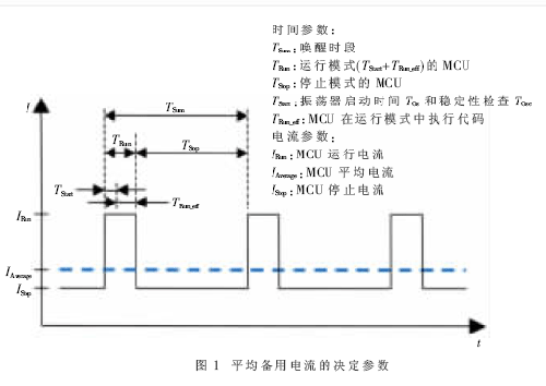
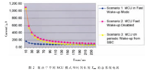
In modern cars, the number of electronic control units (ECUs) continues to grow. Modern electronic components add a number of features that provide drivers with more information and a more comfortable environment that greatly enhances the economic efficiency of the engine while also making the electronics in the car more power efficient. This problem is more serious when the car is turned off than when the car is working properly. When the car is turned off, only the car battery supplies power to the ECU. In order to maximize the life of the battery, it is necessary to have measures to save power during the waiting mode of the car. This paper describes the optimization strategy for the power consumption of door modules that typically require continuous power supply. This article refers to the address: http:// There are up to 70 ECUs in modern cars, from large engine management equipment to tiny Rain Sensor control equipment. When the car is in non-working mode, not all electronic components need to be powered. However, there are still many modules that need to be powered during the time when the car is turned off or the car is locked. For example, a body center controller (BCU) from a car key signal or a door module that must react to a BCU command to control a door lock must be processed. Since automotive empty batteries can cause serious problems after a period of use, most automotive original equipment manufacturers (OEMs) turn the solution into a requirement for waiting current consumption for each ECU operation. They stipulate that the average waiting current consumption per ECU is less than 300μA, and many original equipment manufacturers even require this current consumption to be below 100μA. This current budget must be differentiated according to different ECU components. For example, the main components of the door module are the MCU and the system base chip, including the voltage regulator, the physical interface of the communication bus, and the watchdog. The task is to find the optimal power distribution between different devices at any time. Depending on the function of the door module, the solution for optimizing the task is also different. Typically, the door module controls the window lift, the electronic rear view mirror, the door lock, and the keypad that the driver commands. In addition, it handles BCU communication and, in many cases, passes information to the rear door module. When the car is turned off, the door module must still receive the keypad input command to process the data from the BCU for transmission over the CAN or LIN bus. In order to manage these tasks, it must periodically enter the working mode in order to read the state of the keypad and trigger the watchdog. According to the result, the entire ECU must enter the full operation mode or return current saving mode. Figure 1 illustrates the different currents for all stages in detail. The average system current consumption IAverage is determined by the cycle time Tsum, the length of time the system is operating in the operating mode, and the respective values ​​of the currents IRun and IStop. In summary, the door module has two main methods to minimize IAverage. Method 1: Turn off the MCU power. In this case, the system base chip handles the loop wake up. It will power on the MCU, let the MCU check the above tasks, and let the MCU decide to return to this state or stay in full operation mode. The advantage of this method is that when the SBC consumes sleep current, the power to the MCU is completely turned off. The weakness is that the MCU must wake up periodically, including the start of a very expensive oscillator. Moreover, the pressure of the crystal oscillator during the start-up phase is particularly large, which will affect its service life. Method 2: MCU in low power mode. In this method, the MCU enters a low power mode, but requires constant power. The MCU wakes up periodically, performs the necessary tasks and reacts accordingly. The weakness of this approach is that the SBC and MCU still need to be powered all the time. The advantage is that the MCU can be woken up more quickly, and the time taken for the wake-up phase is completely eliminated according to the function of the MCU. In addition to reducing the current IRun and IStop values, it is more important to minimize the time TRun that the MCU operates in full-service mode. The main components of this parameter are the oscillator start time Tos and the stability check time Tosc. The Freescale S12X Series is designed for quick start after stop mode, and its unique feature is to reduce Tosc and Tosc to almost zero (actually about 50μs). When other MCUs must use an external crystal low frequency oscillator to initiate a periodic interrupt, the S12X can use the built-in RC oscillator to raise the API (automatic periodic interrupt). With the S12X fast wake-up feature, the S12X can be started from the internal PLL oscillator without taking a few milliseconds to start the external crystal oscillator-based oscillator clock. Therefore, with the unique features of the S12X, the startup time during the full operating current of the MCU is almost eliminated. With this method, the average wait current is also greatly reduced. In order to prove that this method can save power, the real life examples are evaluated. Figure 2 shows the common system base chip (SBC) system current and S12X door system current in different wake-up methods and the time parameters shown in Figure 1: Method 1: The SBC periodically wakes up the MCU, and the MCU does not need to supply power during Tstop. Method 2 (a): The MCU needs to be powered continuously and wake up quickly. In this case, the MCU is started with an internal PLL oscillator. Method 2 (b): The MCU needs to be powered continuously, but the fast wake-up is turned off. In this case, the MCU is started with a crystal oscillator. It can be clearly seen that the setting of method 2(b) requires the maximum current anyway, so it is not the best solution for the door mode. Method 2(a) provides Tsum with a minimum current consumption of less than 180ms. As long as the Tsum is no more than 180ms, the method 1 of turning off the MCU power supply and performing the SBC periodic wake-up will be the best choice to minimize power consumption. For the door module, the MCU must check the time Tsum of the state change (usually 20ms to 60ms), depending on the implementation. With the S12X's unique API and fast wake-up capabilities, you can achieve the lowest average system current and power savings, without adding any external components and reducing performance or adding cost. As a result, Freescale's S12X family offers a unique feature that minimizes standby current. When power consumption becomes a selection criterion for automotive OEMs, the S12X Series offers consumers the opportunity to differentiate between original equipment manufacturers in this very important aspect (power consumption) without incurring additional costs. Original equipment manufacturers have the opportunity to win business opportunities in these application areas. The low current consumption when the engine is off is an important requirement for OEMs of continuously powered automotive ECUs. For example, door module manufacturers are facing an increasingly demanding demand for power usage. This article explains how to optimize the average system current by minimizing current consumption and MCU wake-up time. The S12X internal RC-oscillator can be used for automatic periodic interrupt timing to cycle wake up the MCU. The RC-Oscillator's functionality, combined with the S12X fast wake-up feature, provides the user with the most efficient way to maintain the minimum power consumption of the door module application.
In the outdoor lighting section, the global
urban transformation, urban construction, residential construction and road construction
for market demand of high-power, high-brightness, energy-saving LED driver power supply is extremely
large. Isolated Programmable LED Driver no need of Optocoupler and side current control circuit to realize isolating
constant-current output. The circuit structure is very simple.
The advantage of MOSO isolated programmable Industrial Light LED Driver is small
input/output capacitance, small output wave, isolated output, high power
factor, high current precision and high reliability. Fixed output Industrial Light power supply has output open-circuit
protection, over-voltage protection and short-circuit protection.
Dimmable Industrial Light LED Driver built
in 2-in-1 dimming and auto-react:0-10Vdc, PWM signal, dali control is optional.
Architecture
and industrial Light LED Driver adopt
Soft-switching patented technology, high efficiency up to 93%.
Programmable High Bay LED Driver Programmable High Bay LED Driver, Isolated Programmable LED Driver,Programmable LED Driver,Programmable High Bay Light LED Driver Moso Electronics , https://www.mosoleddriver.com