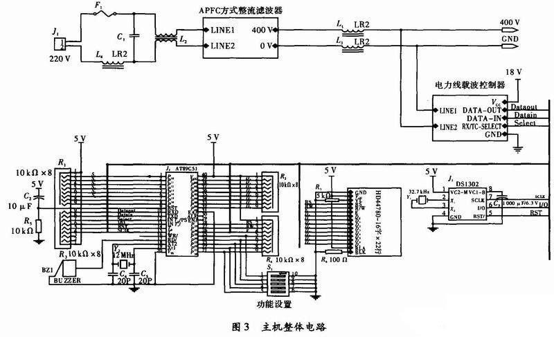
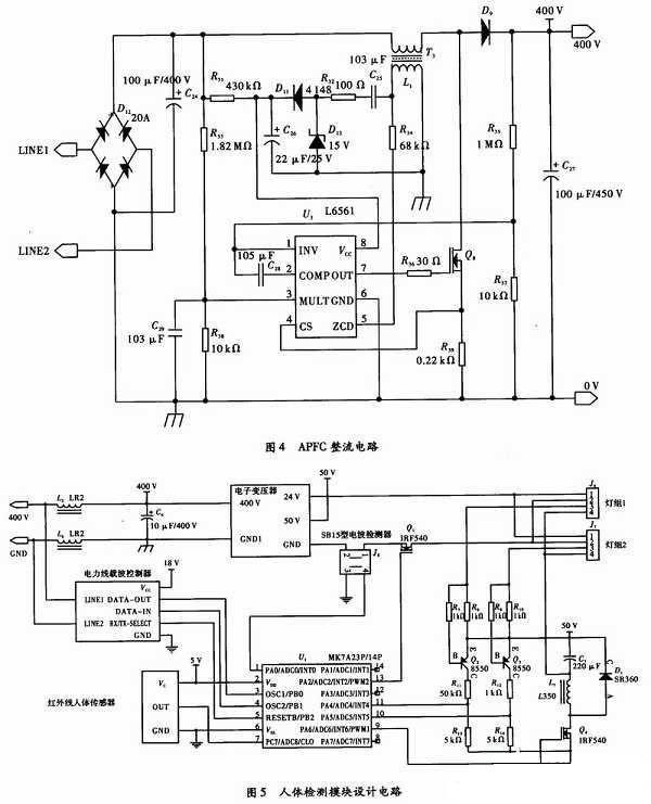
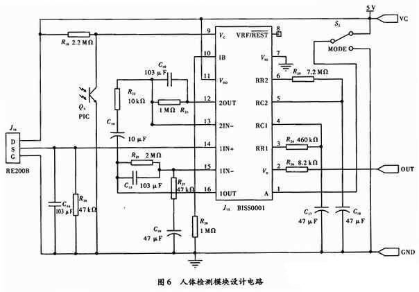
With the growing problem of energy, it has become very important to save energy through various technological means. Lighting facilities, as the most extensive energy-consuming facilities, have significant environmental and economic benefits if they can be more reasonably energy-efficient. In this paper, the pyroelectric infrared sensor and related circuit control are used to realize the idea that “people come to light, people go out, and they don’t go awayâ€. Combine 3 W or 5 W high-power LED technology with high-power spotlights to combine new lighting modes. Using power line carrier technology, the host automatically detects the operation of each lamp, and automatically notifies the host for maintenance if there is damage, thereby reducing maintenance workload. The 400 V DC bus is used for centralized power supply to reduce the rectification and filtering of each lamp, thereby reducing costs and saving energy. Host overall circuit and working principle The power supply mode of the DC 400 V bus is adopted, that is, the input 220 V AC voltage first enters the output DC power of the APFC mode rectification and filtering circuit, and then is connected to the DC/DC electronic buck in each lighting unit through the DC bus, and the final output satisfies the driving force. DC voltage required for power spotlights and LED light sets. The advantage of this method is that a high-efficiency APFC circuit is used to rectify the AC 220 V voltage to obtain a DC voltage of about 400 V. Therefore, there is only one APFC circuit operating frequency in the illumination system composed of N illumination units. Reduced electromagnetic interference. Since the direct current is transmitted on the bus, there is only a resistance loss on the line, which overcomes the voltage drop on the line inductance and can transmit power over a long distance. The power line carrier module is used as a communication module to complete the control of the start, stop, brightness adjustment, automatic switch and the like of the illumination unit of the whole system by the host. This design uses the module built by LM1893. The LM1893 can communicate in half-duplex mode. Both the host and the extension use I2C to transmit and receive data. Control part of the microcontroller C51 and related peripheral circuits. The 16447 x 2 line HD44780LCD is connected to the display as 51 to display the system status in real time. When a lighting unit fails, an alarm is sounded through the buzzer to alert the worker. The DS1302 and related peripheral circuits form an external timing circuit. The advantage is that the DS1302 has two power supply modes. When there is power in the environment, the system power is obtained. When the facility is powered off, it is powered by a low-voltage large capacitor of 1 000μF, and the power consumption of the chip is low enough to meet the normal operation of the chip for about 72 hours. This ensures that the system does not need to reset the time after each power failure. The overall circuit of the host is shown in Figure 3. APFC rectifier filter The high frequency main power supply designed by the L6561 chip is shown in Fig. 4. L6561 is an active power factor correction special chip produced by ST Company. It can easily form a wide voltage input (AC 85~265 V), low harmonic content PFC power supply, can directly drive IGBT tube, and integrate various protection functions. . Due to the high degree of integration, the components required to form the system are reduced, the loss is reduced, and the efficiency is improved. Design of the extension (lighting unit) part The extension part adopts MK7A23P/14P series single-chip microcomputer as the control core. The MCU has strong anti-interference ability, and includes RC oscillator, watchdog and reset circuit. Compared with MCS51 series MCU, it saves a lot of peripheral components. And there is a 1 kB OTP ROM, which is very suitable for various controllers. The part communicates with the host through the power line carrier, and obtains the brightness control command from the host to control the brightness of the lamp or upload the self-test result of the lamp and the working state of the lamp. The human body activity is detected in real time by the pyrolysis infrared human body detection part, thereby controlling the working state of the lamp group after being stepped down by the electronic transformer. The working state of the luminaire is transmitted to the MK7A23P/14P through the SB15 type current detector. When the luminaire is working, there is current, otherwise it is not. The main circuit of the extension is shown in Figure 5. Design of thermocouple infrared human detection control part The human body detection module is composed of a pyroelectric infrared detecting element RE200B, an infrared pyroelectric processing chip BISS0001, and related peripheral devices. The RE200B is the core component that receives infrared rays from the human body and is the signal receiving part of the entire circuit. The overall design of the human body detection module is shown in Figure 6. Q5 is a phototransistor used to detect ambient illumination. When used as lighting control, if the environment is brighter, the triode will be turned on, so that the input of pin 9 is kept low, thus blocking the trigger signal Vs. SW1 is the working mode selection switch. When SW1 is connected to the 1st terminal, the chip is in the repeatable trigger mode. When SW1 is connected to the 2 terminal, the chip is in a non-repeatable trigger mode. The output signal Vo enters the MK7A23P/14P for control. When a person is detected, the Vo output is high, and at this time, the 13 ports of the MK7A23P/14P will output a high level, and the 9 ports output a low level, then Q1 is turned on and Q4 is turned off. At this time, the high-power LED is turned off, the spotlight in the lamp group will start to work, and the current detector sends the detected information to the MK7A23P/14P. When no current is detected, the spotlight is faulty and is fed back to the system host through the power line carrier. . When no one is present, the high-power LED group in the light group is turned on and the spotlight will be turned off. By adjusting the output pulse width of 13 ports and 9 ports, the brightness of the spotlight or high-power LED lamp group can be changed. The 11-port and 10-port scores can be used to determine whether the IED in the lamp group works and feed this information back to the host. Lighting power consumption accounts for a large proportion of the total power generation in various countries. For some organizations with long lighting time and many lighting places, the lighting power consumption accounts for about 40% of all power consumption of the unit. Therefore, it is necessary to guarantee Under the premise of lighting quality, implement lighting energy-saving measures. In this paper, a lighting energy-saving control device is designed. It is proved by theory and experiment that this design scheme is feasible and basically achieves the expected design purpose, and can effectively control the lighting fixtures. Guangdong Ojun Technology Co., Ltd. , https://www.ojunconnector.com