Wireless Charger Car Phone Holder Wireless Charger Car Phone Holder,In Car Phone Holder Wireless Charger,Car Phone Holder And Charger,Phone Car Mount With Wireless Charger Ningbo Luke Automotive Supplies Ltd. , https://www.nbluke.com
Circuit Operation Principle The infusion warmer circuit consists of an astable multivibrator, a temperature detection control circuit, a heating circuit, and a power supply circuit, as shown in Figure 9-151. 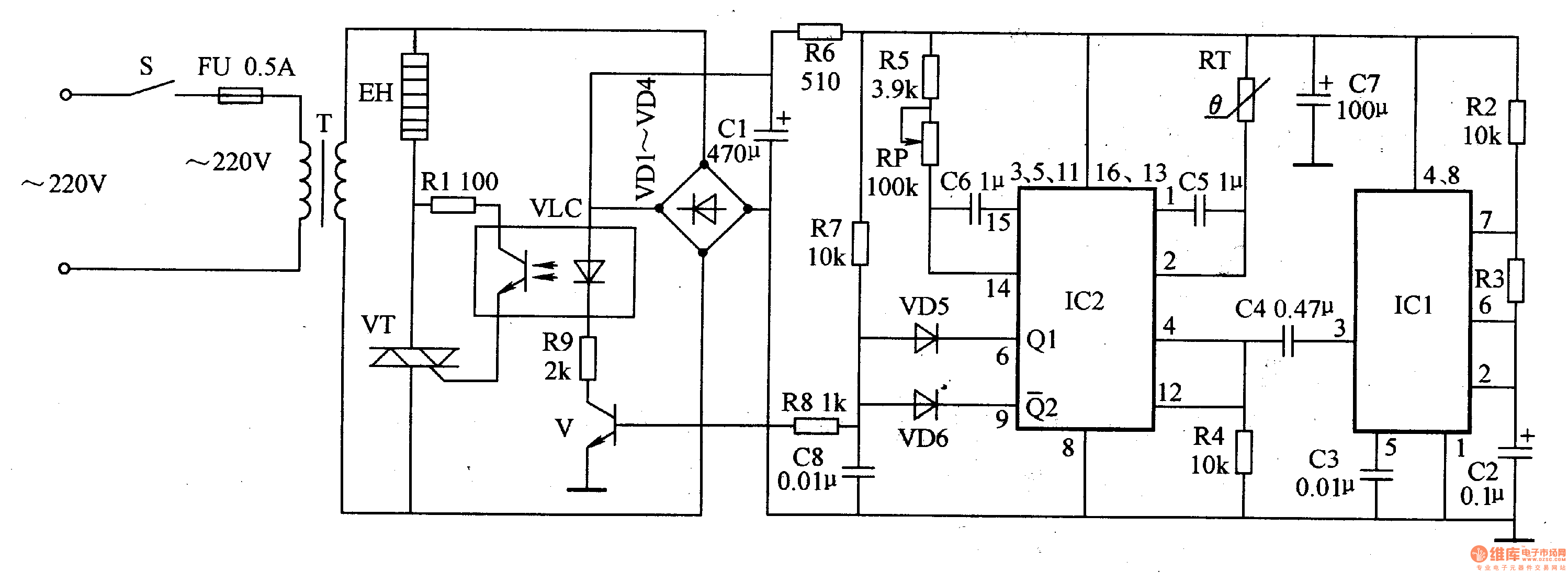
The astable multivibrator circuit is composed of resistors R2, R3, capacitors C2, C3 and a time base integrated circuit ICl.
The temperature detection control circuit is composed of a flip-flop integrated circuit 1C2, a thermistor RT, a potentiometer RP, resistors R4, R5, R7-R9, capacitors C4-C6, a transistor V, and diodes VD5, VD6.
The heating circuit consists of a photorelay VLC, a resistor R1, a thyristor VT, and a heater EH.
The power circuit is composed of a power switch S, a fuse FU, a power transformer T, a rectifier diode VDl-VD4, a filter capacitor Cl, C7, and a current limiting resistor R6.
Turn on the power switch AC 220V voltage after T step-down, VDl-VD4 rectification, Cl filter, one channel provides nearly 18V DC voltage for the LED inside the optocoupler VLC; the other channel is R6 current limit and C7 filter, ICl and IC2 provide operating power.
After the oscillation of the astable multivibrator, the square wave pulse signal is output from the 3 pin of IC1. The pulse signal is differentially processed by C4 and R4, and then input from pins 4 and 12 of IC2, triggering two internal IC2 Steady-state circuit and pulse width comparison. When the 6-pin and 9-pin of IC2 output a high level at the same time, VD5 and VD6 are turned off, V is turned on, the LED inside the VLC is lit, the photo transistor is turned on, the VT is triggered to be turned on, and the EH is energized to start heating. As the temperature of the liquid rises, the resistance of RT begins to decrease. When the heating temperature reaches the set temperature of RP, the 6th pin of IC2 changes from high level to low level, VD5 turns on, V and VLC, VT both. At the end, EH stops heating. When the temperature of the liquid medicine drops to a certain value, the 6th pin of IC2 outputs a high level again, VD5 is turned off, V and VLC, VT are turned on again, and EH starts heating again. The above process is carried out repeatedly, so that the temperature of the chemical solution is kept constant near the set value of RP.
Component selection
Rl-R9 uses 1/4W metal film resistor or carbon film resistor.
RP uses a small synthetic carbon film potentiometer.
Both Cl and C7 use aluminum electrolytic capacitors with a withstand voltage of 25V; C2-C6 uses monolithic capacitors or polyester capacitors.
VDl-VD4 selects 1N4004 or 1N4007 silicon rectifier diode; VD5 and VD6 select lN4148 silicon switch diode or 2AKlO type é”— switch diode.
V selects S9013 or S8050 type silicon NPN transistor.
VT selects two-way thyristors of 1A or more.
VLC uses 4N25 optocoupler.
ICl selects NE555 type time base integrated circuit; IC2 selects MCl4538 or CD4538 type monostable trigger integrated circuit.
T selects 5-lOW, the secondary voltage is l5V power transformer.
EH uses PTC heaters.
S selects 5A, 250V power switch.