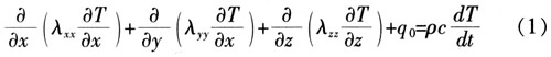
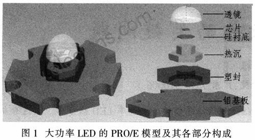
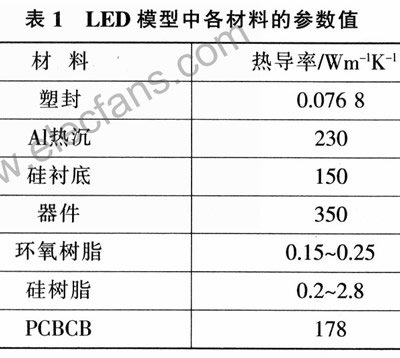
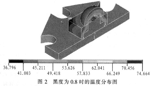
1 Introduction At present, many power LEDs have a driving current of 70 mA, 100 mA or even 1 A, which will cause heat accumulation inside the chip, resulting in a series of problems such as wavelength drift of the emission, decreased light extraction efficiency, accelerated aging of the phosphor, and shortened service life. The industry has made a lot of efforts on the heat dissipation of high-power LEDs: through optimizing the design of the epitaxial structure of the chip, using the surface roughening technology to improve the quantum efficiency inside and outside the chip, reducing the lattice oscillation caused by the non-radiative recombination, and fundamentally reducing the heat dissipation. Component load; by optimizing the package structure and materials, the aluminum-based metal core printed circuit board (MCPCB) is selected, and ceramics, composite metal substrates, and the like are used to accelerate heat dissipation from the epitaxial layer to the heat dissipation substrate. Most manufacturers also recommend using heat sinks in high-performance requirements, relying on strong convection heat dissipation to promote high-power LED heat dissipation. Despite this, a single LED product is currently only at the level of 1 to 10 W, and the heat dissipation capacity still needs to be improved. A considerable amount of research has focused on finding high thermal conductivity heat sinks and packaging materials, but when the LED power reaches above 10 W, this concern has encountered considerable resistance. Even if the air-cooled strong convection method is applied, the cost advantage is sacrificed and satisfactory changes are not obtained. Discuss the influence of factors such as the thermal conductivity of the existing structure, LED package and heat sink material on its maximum power, and find the key factors affecting the heat dissipation of the LED. The research method is finite element thermal analysis. This method has experimentally verified the difference between the LED finite element model and its real device, and proved that it is accurate and feasible within the error tolerance. 2 Building a model 2.1 Finite element thermal analysis theory The transient temperature field variable T(x, y, z, t) in the three-dimensional Cartesian coordinate system satisfies: Where: T/x, T/y, T/z is the temperature gradient along the x, y, z direction; λxx, λyy, λzz is the thermal conductivity; q0 is the heat generation per unit volume; Ïc is the density and specific heat capacity Product: dT/dt is the rate of change of temperature with time. Where: Vx, Vy, Vz are the medium conduction rates. For steady-state thermal analysis, T/t = 0, and equation (1) can be reduced to: According to the formula (3), the boundary conditions and the initial conditions, the iterative method or the elimination method is used to obtain the thermal analysis result. 2.2 Establishment of geometric models Figure 1 shows a high-power LED pattern based on a common 1 w high-power LED size, snail-sealed aluminum heat sink, and the base is attached to the MCPCB aluminum substrate. Main data: The chip size is 1 mm × 1 mm × O.25 mm, and the lens is a hemisphere with a diameter of 13 mm. The silicon substrate is a regular hexagonal prism with a side length of 17 mm and a height of 0.25 mm. The MCPCB is a hexagonal aluminum substrate with a diameter of 20 mm and a height of 1.75 mm. 2.3 Establishment of finite element model The model is calculated using ANSYSl0.0. For ease of analysis, the model is assumed to be: The LED input power is 1 W, and the light efficiency is 10%; the components outside the package (including the MCPCB, the ceramic package, and the outside of the heat sink) are cooled by convection with air; the thermal convection coefficient of the device to the outside is 20. The working environment temperature is 25 ° C; the device meets the conditions for steady state finite element thermal analysis using ANSYS software; the maximum junction temperature is selected to be 125 ° C. The parameters of various materials are shown in Table 1. 3 Analysis of the impact of various factors on heat dissipation 3.1 The influence of thermal radiation coefficient on LED heat dissipation Figure 2 is a temperature cloud diagram when the surface blackness is 0.8. According to Stephen Boltzmann's law, the relationship between the irradiance j* and the temperature T: j* = εσT4. Where ε is the emissivity of the black body; σ=5.67×10⁻⁸w/(m2·k4), which is called the Stephen-Boltzmann constant. Therefore, it can be seen that the higher the temperature, the greater the irradiance. When the input power is 1 W, the thermal energy radiated through the surface radiation is 7.63×10⁻⁴W, which is only 1.63‰ of the total thermal power; when the power reaches 2 W, the thermal energy radiated by the radiation only accounts for 6.33‰. Therefore, changing the thermal radiation coefficient has little effect on improving the heat dissipation capability. The key to heat dissipation is to improve the other two heat dissipation modes: heat transfer and heat convection. Despite this, some manufacturers have painted the outer surface of the LED device black to maximize the use of radiation to dissipate heat. 3.2 Influence of thermal conductivity on heat dissipation of LED Only consider heat conduction and convection, change the different package filling materials such as silicone. The results are shown in Figure 3. Even when an epoxy resin encapsulating material with a thermal conductivity of up to 7 Wm-1K-1 is found, the chip temperature does not decrease much when compared with an epoxy resin encapsulating material with a thermal conductivity of 0.25 Wm-1K-1. The temperature of the aluminum substrate only dropped by 2.271 ° C, and the maximum power was only increased by 0.69 W. In fact, commercially available transparent silicone encapsulants with thermal conductivity values ​​above 7 Wm-1K-1 are currently not reported in the literature. The distribution cloud diagram is shown in Figure 4.