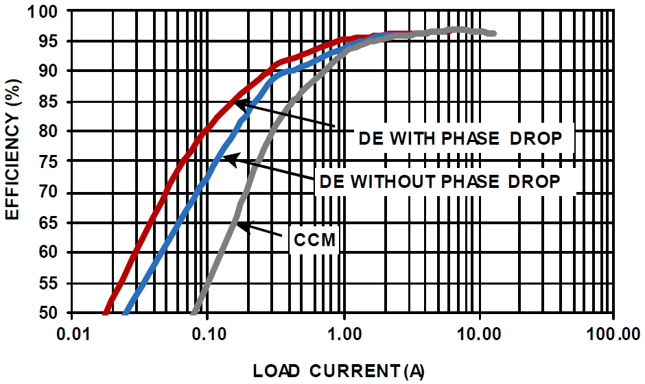
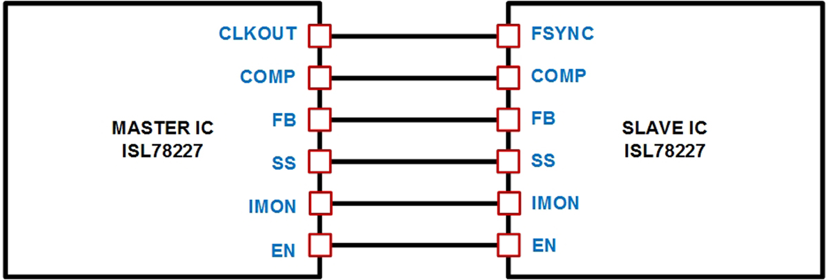
To meet the requirements of these high voltage applications, a new generation of AEC-Q100 certified synchronous boost controllers has emerged on the market. This controller is designed to boost the 12V battery voltage, withstand spikes up to 60V, and with the high reliability required for new models. Although 12V lead-acid batteries are still the mainstream of automotive power supplies, some new applications require higher voltages, such as trunk audio power amplifiers and window defrosters. This article refers to the address: http:// This article describes a pair of easy-to-use 2-phase 55V synchronous boost controllers that produce 24V, 36V, or 48V rails in automotive environments with only 12V supplies. We'll look at some of the key features of their integration, including comprehensive protection features that help optimize the solution to reduce costs and increase efficiency, security, and reliability. We will also discuss an integrated PMBus interface that provides advanced control, telemetry, and diagnostic capabilities and simplifies the task of implementing ISO 26262 compliance. Raise the 12V battery voltage One of the challenges that system design engineers have always faced is how to achieve greater power efficiency while minimizing board space. The ISL78227 and ISL78229 55V synchronous boost controllers solve this problem by integrating an advanced FET driver that adaptively adjusts the number of switchings to prevent cross conduction when simplifying power stage design. The 2-phase configuration of these two controllers reduces ripple current, allowing for smaller input and output capacitors, which helps reduce board footprint. Two controllers can be used in parallel to increase the number of phases to four to support higher power output levels. The ISL78227 and ISL78229 feature a PMBus interface that supports a wide 50kHz to 1.1MHz operating frequency range and can be configured with smaller external components to optimize operating frequency to help increase efficiency or minimize board space. They include many features designed to maximize efficiency, which is important because the peak output current of a 12V battery will exceed 30A at 400W load. Synchronous FET for output rectification Since most buck converters have low output voltages, FETs are often used in buck converters instead of diodes for output rectification. In this configuration, a large percentage of the power loss in generating the output voltage comes from the voltage drop across the rectifying element. Using a synchronous FET that can be turned on and off at the appropriate time instead of an output rectifier diode can greatly increase efficiency. This is because FET losses typically only account for a small fraction of the rectifier diode losses. In a buck converter, the reference voltage of the synchronous FET is a ground voltage, so the drive circuit is relatively simple. Synchronous FETs offer a number of benefits to the boost configuration. In boost converter applications, the output voltage is typically several times the input voltage, so the power loss produced by the output rectifier components is a small percentage of the total output power. Boost converters benefit from increased efficiency of synchronous FETs, while synchronous FETs provide bidirectional current, which supports continuous mode operation (even under light load conditions) – an important advantage for applications requiring low electromagnetic interference (EMI). Bidirectional current flow is also an important capability to achieve efficient envelope tracking, which we will discuss below. In addition, the use of a synchronous FET does not preclude operation in discontinuous mode. The boost controller is capable of detecting negative current flow and has the option of disabling the synchronous FET to simulate the function of the synchronous rectifier diode. Improve light load efficiency through diode simulation Audio signals often change dramatically in a very short period of time. At this point, the amplifier may require a high-power burst, and a burst of very low power may be needed in the next moment. It may even be muted during an audio session. When this happens, the power consumption of the amplifier will drop significantly, because of this, the power demand of the boost regulator will also drop to a lower value. In fact, under light load conditions, the boost inductor current can be reduced to zero. When this happens, the output voltage (boost voltage) of the inductor is higher than the input voltage (battery voltage). If the sync FET remains on during this condition, the current will begin to flow back through the inductor and get the charge from the output capacitor. Figure 1. Efficiency vs. load comparison diagram, 2-phase boost configuration, three operating modes, fSW=200kHz, VIN=12V, VOUT=36V, TA=+25°C English Chinese translation EFFICIENCY efficiency DE WITH PHASE DROP diode simulation (with phase reduction) DE WITHOUT PHASE DROP diode simulation (no phase reduction) LOAD CURRENT (A) load current These 55V boost controllers include an optional circuit to avoid this reverse conduction loss by having the synchronous FET simulate the current blocking behavior of a real diode. This smart diode operation, called Diode Emulation Mode (DEM), acts to turn off the synchronous FET when it senses that the inductor current begins to flow in the wrong direction. If the controller enters diode emulation mode and the load is still decreasing, the controller will enter a pulse omission mode to reduce the number of switching cycles, thereby increasing its efficiency at very light loads on the output. Although DEM can improve efficiency under light load conditions, it also presents some electromagnetic interference challenges due to changing switching characteristics. To avoid electromagnetic interference problems, it is often desirable to maintain continuous conduction mode (CCM) operation. Of course, this will sacrifice the efficiency gain brought by diode simulation, as shown in Figure 1. However, in applications such as audio amplifiers, an alternative to achieving light load efficiency gains is to have the amplifier power supply use envelope tracking to track input requirements. Forced PWM mode of operation Many power system applications require that the converter's switching frequency be kept constant to minimize the possibility of interference. Due to this requirement, the ISL78227 and ISL78229 can also operate in PWM mode (no pulse omitted). However, in forced PWM mode, reverse current may flow, such as entering the pre-biased output state at startup or when the output voltage rises above the expected voltage. In a typical system, there is no way to limit the reverse current, which can damage the sync FET. The ISL78227 and ISL78229 solve this problem by providing reverse current limiting. Limiting negative current reduces output voltage transients and increases system reliability. As a result, the design engineer can configure the boost controller to force the PWM mode without worrying about the reverse current being out of control. Improve light load efficiency with Phase Shedding The ISL78227/29 synchronous boost controller supports 2-phase boost operation, and we can connect the two devices for four-phase operation (see Figure 2). Under heavy load conditions, the main system losses are due to conduction losses and switching losses, but under light load conditions, switching losses begin to be a major loss factor. To increase efficiency, both controllers can be configured to monitor system current levels. If the load drops below a certain threshold, the controller subtracts one phase, which reduces switching losses under light load conditions. The phase shielding process is completed in 15 switching cycles to prevent load transients. If the load subsequently increases above the threshold, then immediately add a phase to manage the increased load. KNB1-32 Miniature Circuit Breaker
KNB1-32 Mini Circuit breakers, also named as the air switch which have a short for arc extinguishing device. It is a switch role, and also is a automatic protection of low-voltage electrical distribution. Its role is equivalent to the combination of switch. Fuse. Thermal Relay and other electrical components. It mainly used for short circuit and overload protection. Generally, According to the poles, mini Circuit breaker can be divided into 1P , 1P+N , 2P, 3P and 4P.
KNB1-32 Miniature Circuit Breaker,KNB1-32 Electronics Miniature Circuits Breaker,KNB1-32 Automatic Miniature Circuit Breaker,KNB1-32 Mini Circuit Breaker Wenzhou Korlen Electric Appliances Co., Ltd. , https://www.zjmoldedcasecircuitbreaker.com