Energy-saving technology advantages and application of double-fed motor in frequency converter and PLC
1. Doubly-fed motor control theory and energy-saving technology
1.1 Advantages of doubly-fed motors
The doubly-fed electric motor is not only a category of asynchronous machines, but also can be called an alternating current excitation motor (AlternaTIng Current Exc itaTIo n Mo to r ACEM) or an asynchronous synchronous motor (Async hro nized Sync hro no us Mo to r). Because it contains separate field windings, the power factor can be adjusted by increasing the excitation like a synchronous motor during use. Synchronous motors are actually DC-excited, so it can only perform a current amplitude adjustment, so it is generally only capable of regulating reactive power. The doubly-fed motor can adjust to three quantities: adjustable excitation current amplitude, variable excitation frequency, and phase changeable. This shows that in order to achieve the purpose of speed regulation, the doubly-fed motor can change the speed of the electromechanical by changing the excitation frequency. Similarly, when the load is abrupt, the speed of the electromechanical can be changed by controlling the frequency of the excitation, and the kinetic energy generated by the rotor can be fully utilized and the load can be absorbed or released. Compared with synchronous motors, doubly-fed motors are capable of adjusting the power factor by changing the magnitude of the current excited by the rotor. Therefore, in the process of using AC excitation, not only the regulation of reactive power but also the condition of active power can be performed. The advantage of the doubly-fed motor is mainly because it uses an AC excitation power source that can be adjusted.
1.2 Hengshi in power energy-saving technology
The motor power can be mainly divided into three types: reactive power, active power, and apparent power. The main point of Hengshi's power in use is that when the active power changes, the power factor of the motor can be adjusted, and finally the apparent power of the motor is controlled to a fixed value. The advantage of this method is that the motor can transmit the remaining motor capacity as reactive power to the grid when it is lightly loaded, and when the motor is overloaded, the power factor of the motor can be adjusted to be similar to the unit power, and The reactive power of the grid is not absorbed. Similarly, the constant vision power can also be used in fans and pumps. The main reasons are:
(1) In the process of working in China's power plants and steel plants, the equipment with the highest electricity consumption is mainly air conditioners, fans and pumps. Therefore, it is very necessary to implement energy-saving measures for fans and pumps, and the energy-saving effect will be very high. obvious. The state has regulations on the technical equipment for all enterprises to produce, namely reliability and efficiency. However, there is not much emphasis on the waste of resources in the production process, so it is very necessary to implement energy-saving measures for pumps and fans.
(2) The efficiency of the use of power in China is relatively low. The main reason is that there is a phenomenon of “small horse-drawn carts†in the production process. When the relevant design institutes are designing, in order to take as little responsibility as possible, they adopt a relatively conservative and backward design scheme, and the parameters used are beyond the actual size, so that the margin is too large. The pressure and flow coefficients are also too large. However, in order to reduce their own risks, manufacturers are increasing the pressure and flow coefficient. This increase in layers and layers eventually leads to the appearance of the “small horse-drawn cart†phenomenon, which also makes the product deviate from the original design. Reduced efficiency. However, the use of constant power has just made up for this shortcoming, and it also provides reactive power to the factory.
2. Application technology of PLC and inverter
In the energy-saving control system of the doubly-fed electric motor, careful care and caution should be taken when selecting the excitation power of the controller and the rotor, because their quality is directly related to the reliability, stability and energy saving of the system. Due to their unique advantages, PLCs and general purpose drives are ideally suited for use in doubly-fed motor control systems.
2.1 PLC selection
When selecting the PLC model, first analyze and determine the requirements of the PLC's input/output ports and communication ports. Then, according to the requirements of the doubly-fed electric energy-saving control system itself, all the input/output signals in the system are summarized and classified, and the I/O address is allocated according to the requirements of the input/output points of the PLC to ensure each input. / The output signal can accurately correspond to the PLC's input/output relay, and finally the PLC model is confirmed based on the result.
The variety of PLC products from Siemens is very diverse. The S7 200 is a small PLC and a third-generation product. There are several aspects about the features of the S7 200:
(1) Powerful features. The S7 200 has five CPU modules and can be expanded to seven. It can also be expanded to 248 digital I/Os and has more than 30 KB of data storage space. A collection of six high-speed counters as well as a pulse generator and a pulse width modulator greatly improve the efficiency of the work. Can achieve the customization of the PID parameters.
(2) Advanced program structure. The program structure included in the S7 200 is very simple. The main program, subprograms and interrupt programs included in the software for programming are saved separately. The subroutine can also use the input and output variables as the interface of the software, which is beneficial to achieve the purpose of structured programming.
(3) Flexible and convenient addressing. Each part of the structure included in the S7 200 can be read and written in bits, bytes, words, and double words, such as bit memory, variable memory, input and output structures, and so on.
(4) The programming software is powerful and easy to use. The programming software STEP7 Mic ro/WIN V4.0 contains three parts: ladder diagram, statement list and function block diagram programming language. While the S7 200 is operating, its commands are very functional, but they are also easy to master.
(5) Powerful communication functions. The S7 200 CPU module for programming or communication is an RS 485 interface and has one or two.
2.2 Selection of frequency converter
The frequency converter type recommends Siemens Mic roMaster440/420. As a classic based on three-phase AC speed control motor series, Mic roMaster440/420 is mainly controlled by microprocessor. Air filter output mainly relies on bipolar insulated gate transistor, which has strong comprehensive operation capability. It can bring outstanding reliability to the equipment. At the same time, the internal module structure of this inverter is flexible, the motor protection function is in place, and it is equipped with RS485/232C built-in interface and PI closed-loop controller for process control, which meets the requirements of user-defined I/O terminals and utilizes magnetic flux. The current is used to dynamically control the frequency conversion characteristics, and the torque output can be completed during the low frequency period, and the high speed current limit is not tripped.
Mic roMaster440 is equipped with the energy-saving control of the doubly-fed motor, which can meet various types of frequency conversion requirements of the system, such as separate control of voltage increase and frequency, and complete two-way adjustment of power and speed factor, which are excellent in various system control. The Siemens Mic roMaster 440 with output power of 0.74-90kW can play its own advantages in the higher power field. With the sensorless automatic vector control of ECO energy-saving control, it can effectively enhance the control functions such as advanced adsorption and delayed release of mechanical brake. To ensure that the lift continues to operate stably. Finally, Mic roMas.ter440 is also optimized for conveyor belt fault detection, which ensures the safe operation of the production line. The PID controller with custom parameter function is used to realize the master-slave control, which is suitable for the multi-machine coaxial drive mode.
3. Design of energy-saving control system for doubly-fed electric motor based on PLC and frequency converter
Through the structure diagram of the doubly-fed engine system (see Figure 1), we can find that the controller system mainly consists of PLC as the core, control the inverter and switching circuit, and perform circuit detection before frequency conversion adjustment. The touch screen can bring an intuitive human-computer interaction instruction interface to the control system, and adjust the system parameters and the motor state at any time. The control personnel use the touch screen to observe the system operation. The current frequency, phase and voltage increase corresponding to the circuit detection can effectively control the rated voltage and power, and the motor revolution can also be well mastered. The circuit detection function transmits the voltage data to the PLC through the signal, and then the system analyzes the data. And reasonable control. The starter acts on the motor. When the motor is soft-started, the control circuit switches mode. Only when the system is in the doubly-fed mode will the double-fed motor be successfully started. The energy-saving algorithm and control mode of the system are programmed into the PLC, and the adjustment of the parameters is used to control the overall state of the motor, and finally achieve the purpose of energy-saving control.
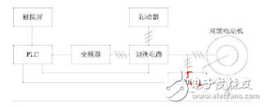
Figure 1 Structure of the energy-saving system of the doubly-fed engine
3.1 main circuit and control circuit design
The main circuit constitutes a loop referring to the doubly-fed motor and the DC generator. It should be noted in the design that when the DC generator is loaded by the doubly-fed motor, the latter stator winding needs to be connected to the 50 Hz grid and is connected to the rotor winding. The inverter supplies power, and the current is input to the phase and frequency by the rotor winding, thereby achieving the mastery of the power and speed of the doubly-fed motor. The design of the energy-saving control system needs to designate the PLC as the controller to receive and verify the circuit signals and analyze the current voltage parameters of the motor. Finally, the PLC will execute the internal algorithm according to the parameters, and control the power output of the contactor coil and the inverter to fully display Doubly-fed motor operation.
3.2 Design of transient parameter detection circuit for doubly-fed motor
The speed detection is composed of pulse isolation and rotary encoder. The encoder is responsible for collecting the speed parameter and converting it into a pulse signal for analysis and processing by the pulse isolation circuit. It becomes a pulse signal that can be recognized by the PLC. The PLC processes the feedback information. After optimization, it is converted into a pulse signal again to set a reasonable speed for the motor. In the design, the importance of power factor in system control should be fully considered. The power factor can be monitored in real time. The reason is that the cos function is an even function, and the positive and negative power factors will take a positive value, so the operator It is difficult to judge the load condition from the power factor. In the design, the current and voltage can be used as the basis to judge the power factor of the line leading and backward. At the same time, the power factor acts as a nonlinear function and cannot be bridged by line simulation. For this, the microprocessor can be designed for power factor.
3.3 Inverter capacity release circuit design
The significance of the capacity release of the inverter is to maintain the safe operation of the inverter. The design principle is based on not changing the capacity. The current general-purpose inverter condition is used to enhance the current output, so that the current meets the system control requirements of the doubly-fed motor. Inverter capacity release In the design, the step-down method can be used to connect the rotor to the secondary side of the voltage of the motor and the primary side of the transformer, so that the doubly-fed motor is continuously stable in the range of 1350 rpm. If the motor power factor is 1, then the transformer The secondary side must be connected to a voltage above 13V and a current above 9A, and the output power of the inverter is 39V and 3A. After the rotor connection is completed, the voltage and current of the inverter are increased by 3 times, which realizes the capacity of the inverter to be released 3 times. In this design stage, it should be noted that according to the rotor induction and voltage and current characteristics of the doubly-fed motor, The inverter voltage output is in the low frequency state, so the step-down transformer used in the system needs to be replaced by a dedicated low-frequency transformer.
4 Conclusion
After long-term development of motor energy-saving technology, it has achieved many achievements today. It plays a wide range of fields, such as petrochemical, metallurgy, light industry, etc. The demand for motor energy-saving technology is increasing day by day. Through the comprehensive optimization of the system design, the frequency conversion speed control equipment is promoted, and the production of speed adjustment and flow regulation is adapted to various needs. The effective use of the motor system can provide a strong guarantee for the capacity equipment and the overall operation of the motor system, and further research and development. Motor capacity, strengthening power for manufacturing. The continuous and stable operation of the motor control system needs to rely on perfect process control and energy allocation. China should further promote the motor energy-saving technology to help enterprises obtain higher profit margins and production safety guarantees.
5 inch screen, square model & vertical model.
Dynamic temperature measurement Face Recognition Terminal, which performs identity recognition based on the facial feature information of the person, and uses an infrared sensor to measure and record the body temperature in real time.
Applicable to office building, community, park, campus, and other public places such as access control attendance and temperature identification management.
Time Card Punch Machine,Face Recognition Terminals,Face Recognition Terminal,Infrared Temperature Instrument
Guangzhou HangDeng Tech Co. Ltd , https://www.hangdengtech.com