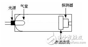
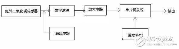
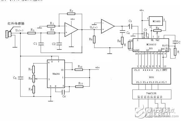
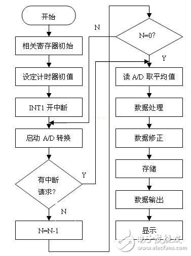
With the progress of human society and the development of science and technology, people's living standards have been rapidly improved, and the scale of industrial production has also expanded rapidly, but at the same time, the carbon dioxide emissions have doubled, such as the greenhouse effect, the acceleration of land desertification, etc. It affects and destroys the living environment of human beings. In addition, carbon dioxide is the main raw material for crop photosynthesis, and its content directly affects the growth of crops. In recent years, with the enhancement of people's awareness of environmental protection, the advancement of science and technology, how to quickly detect the content of carbon dioxide, and reduce the emission of carbon dioxide, it has become a special concern of governments at all levels and people of insight, so research and design carbon dioxide detection. The circuit is very important. At present, the methods for detecting carbon dioxide mainly include chemical methods, electrochemical methods, gas chromatography, volumetric titration, etc. These methods generally have problems such as high price and poor universality, and the measurement accuracy is still low. The sensor method has the advantages of safety, reliability, fast direct reading, and continuous monitoring. At present, various carbon dioxide sensors for detection mainly include solid electrolyte type, barium titanate composite oxide capacitor type, and conductivity change type thick film type. These sensors have poor selectivity to gases, are prone to false alarms, require frequent calibration, and are used. Shortevity, such as short life. The infrared absorption type carbon dioxide sensor has the characteristics of wide measuring range, high sensitivity, fast response time, good selectivity and strong anti-interference ability. To this end, the design uses an infrared absorption type carbon dioxide sensor, and the entire circuit design is simple and easy to use, fast and direct reading, and low in price. 1 How the detection circuit works 1.1 Working principle of infrared absorption type carbon dioxide gas sensor The infrared absorption type CO2 gas sensor is based on the principle that the absorption spectrum of the gas differs depending on the substance. The chemical structures of different gas molecules are different, and the absorption degree of infrared radiation of different wavelengths is different. Therefore, when infrared radiation of different wavelengths is sequentially irradiated to the sample material, the radiation energy of certain wavelengths is selectively absorbed by the sample material and becomes weak, generating infrared rays. Absorption spectrum, so when the infrared absorption spectrum of a substance is known, the absorption peak of the substance in the infrared region can be obtained therefrom. When the same substance has different concentrations, there are different absorption intensities at the same absorption peak position, and the absorption intensity is proportional to the concentration. Therefore, by measuring the influence of the gas on the wavelength and intensity of the light, the concentration of the gas can be determined. According to Bill Lambert's law, the relationship between output light intensity, input light intensity, and gas concentration is: In the middle The concentration of the gas can be known by detecting the relevant data. Figure 1 Carbon dioxide sensor probe structure The structure of the infrared carbon dioxide sensor probe is shown in Figure 1. It is composed of infrared light source, measuring gas chamber, adjustable interference filter, photodetector, light modulation circuit and amplification system. The infrared light source is made of nickel-chromium wire, which emits 3 to 10 μm of infrared light when it is heated by electricity, and contains a strong absorption peak of CO2 gas at 4.26 μm. In the gas chamber, the carbon dioxide absorption source emits light of a specific wavelength, and the detector detects the absorption of infrared light by carbon dioxide. The interference filter is adjustable, adjusting the wavelength of the light wave through which it can change, thereby changing the strength of the signal detected by the detector. The infrared detector is a film capacitor. After the infrared energy is absorbed, the temperature of the gas rises, causing the pressure in the chamber to increase. The distance between the two poles of the capacitor is changed, and the capacitance value changes accordingly. The greater the concentration of CO2 gas, the greater the change in capacitance. 1.2 Design principle of detection circuit Figure 2 block diagram of the detection circuit The block diagram of the detection circuit design is shown in Figure 2. The detection circuit is composed of an infrared carbon dioxide sensor, a digital filter circuit, an amplifying circuit, a steady current circuit, a single chip system, and temperature compensation. The basic principle of the design is that the infrared carbon dioxide sensor converts the detected carbon dioxide gas concentration into a corresponding electrical signal, and the output electrical signal is filtered, amplified, input to the single-chip microcomputer system, and processed by temperature and pressure compensation, etc., by the single-chip microcomputer. The system output sends the display device to display its measured value. 1.3 Design of the detection circuit Figure 3 Carbon dioxide detection circuit diagram According to the above design principle, the designed carbon dioxide detection circuit is shown in Figure 3. The working principle is that the concentration of carbon dioxide gas is first detected by the infrared sensor and converted into an electric signal, and the filter circuit extracts the electric signal and outputs it to the amplifying circuit, which is processed by the single chip system, and then sent to the display circuit by 74AC138 to realize the carbon dioxide. Detection of gas concentration. In the circuit, R1, R2, R3, R4, C1, C2 and op amp constitute a filter circuit [2], which introduces both negative feedback and positive feedback. When the signal frequency tends to zero, the positive feedback is weak because the reactance of C1 tends to infinity; when the signal frequency tends to infinity, the reactance of C2 tends to zero. This ensures that when the signal frequency is at any value between zero and infinity, the filter circuit can normally extract the corresponding electrical signal. The amplifying circuit after the filter circuit functions to amplify the signal output from the filter circuit to a certain extent to drive the load. R6 and C4 are connected in series to form a correction network for phase compensation of the circuit. The MCU system is mainly composed of MC14433 and 8031. The MC14433 is a double integral A/D conversion chip, which is connected with the 8031 ​​MCU. The conversion result of MC14433 is connected to P1.0-P1.3 of 8031, and the strobe output pulse DS1-DS4 is connected to P1.4-P1.7 of 8031. The conversion result flag EOC is connected to the update conversion control signal input line DU on the one hand, and to the interrupt input line INT1 of the 8031 ​​on the other hand, indicating that the single chip can read the result of the A/D conversion by using the interrupt mode, or can use the query mode. . The final result is sent to the 74AC138 and drives the digital tube to display the specific value [3][4]. 2 detection process flow diagram The flow chart of the detection processing program is shown in Figure 4. Using MCS series assembly language [5] programming, due to the guarantee of hardware design, the whole system can work in both the loop query mode and the interrupt management mode. Figure 4 detection process flow chart 3 Conclusion The design has been successfully applied to the Flower Demonstration Park of Yan'an Agricultural Science Institute, and the operation effect is good. Practice has proved that the detection circuit is simple in operation, numerical display, small in size and easy to carry, very intuitive, continuous and rapid detection, and can detect the content of carbon dioxide gas in indoor and outdoor various occasions at any time. The circuit is simple in design, low in price and universal in general, and overcomes the shortcomings of frequent calibration, short service life and high price.
Piezoelectric ceramic disc
Quick delivery
High performance
Application: flow meter measurement
There are many kinds of USF used in closed pipeline according to the measuring principle, and the most commonly used are propagation time method and Doppler method. Among them, time difference ultrasonic flowmeter is used to measure fluid flow by the principle that the time difference of sound wave propagating downstream and countercurrent is proportional to the velocity of fluid flow. It is widely used in raw water measurement of rivers, rivers and reservoirs, process flow detection of petrochemical products, water consumption measurement of production process and other fields. According to practical application, time-difference ultrasonic flowmeter can be divided into portable time-difference ultrasonic flowmeter, fixed time-difference ultrasonic flowmeter and time-difference gas ultrasonic flowmeter.
Ultrasonic flow-meters use at least two transducers aligned so that ultrasonic pulses travel across the flow of liquid or gas in a pipe at a known angle to the flow.
Technical data:
Electromechanical coupling coefficient Kp: > 0.62
Dielectric Loss tg δ: <2%
Nominal Piezo discs for ultrasonic flowmeter:
OD14.2*1MHz PZT-51
OD14.6*1MHz PZT-51
OD15*1MHz PSnN-5
OD15*2MHz PSnN-5
OD20*2MHz PSnN-5
OD15*1MHz PZT-51
OD15*2MHz PZT-51
OD20*2MHz PZT-51
Size, Frequency and Electrode on request.
Piezoelectric Discs For Flowmeter Sensor Piezoelectric Ceramic Disc,Piezoelectric Discs For Flowmeter Sensor Zibo Yuhai Electronic Ceramic Co., Ltd. , https://www.yhpiezo.com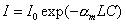
![]() Is the molar molecular absorption coefficient; C is the concentration of the gas to be tested; L is the length of action of the light and gas (sensing length). Transform the above formula:
Is the molar molecular absorption coefficient; C is the concentration of the gas to be tested; L is the length of action of the light and gas (sensing length). Transform the above formula: