Absolute rotary Encoder measure actual position by generating unique digital codes or bits (instead of pulses) that represent the encoder`s actual position. Single turn absolute encoders output codes that are repeated every full revolution and do not output data to indicate how many revolutions have been made. Multi-turn absolute encoders output a unique code for each shaft position through every rotation, up to 4096 revolutions. Unlike incremental encoders, absolute encoders will retain correct position even if power fails without homing at startup.
Absolute Encoder,Through Hollow Encoder,Absolute Encoder 13 Bit,14 Bit Optical Rotary Encoder Jilin Lander Intelligent Technology Co., Ltd , https://www.landermotor.com
Circuit Operation Principle The electronic painkiller circuit consists of a high voltage generator, a pulse generator, and an output circuit, as shown in Figure 9-32. 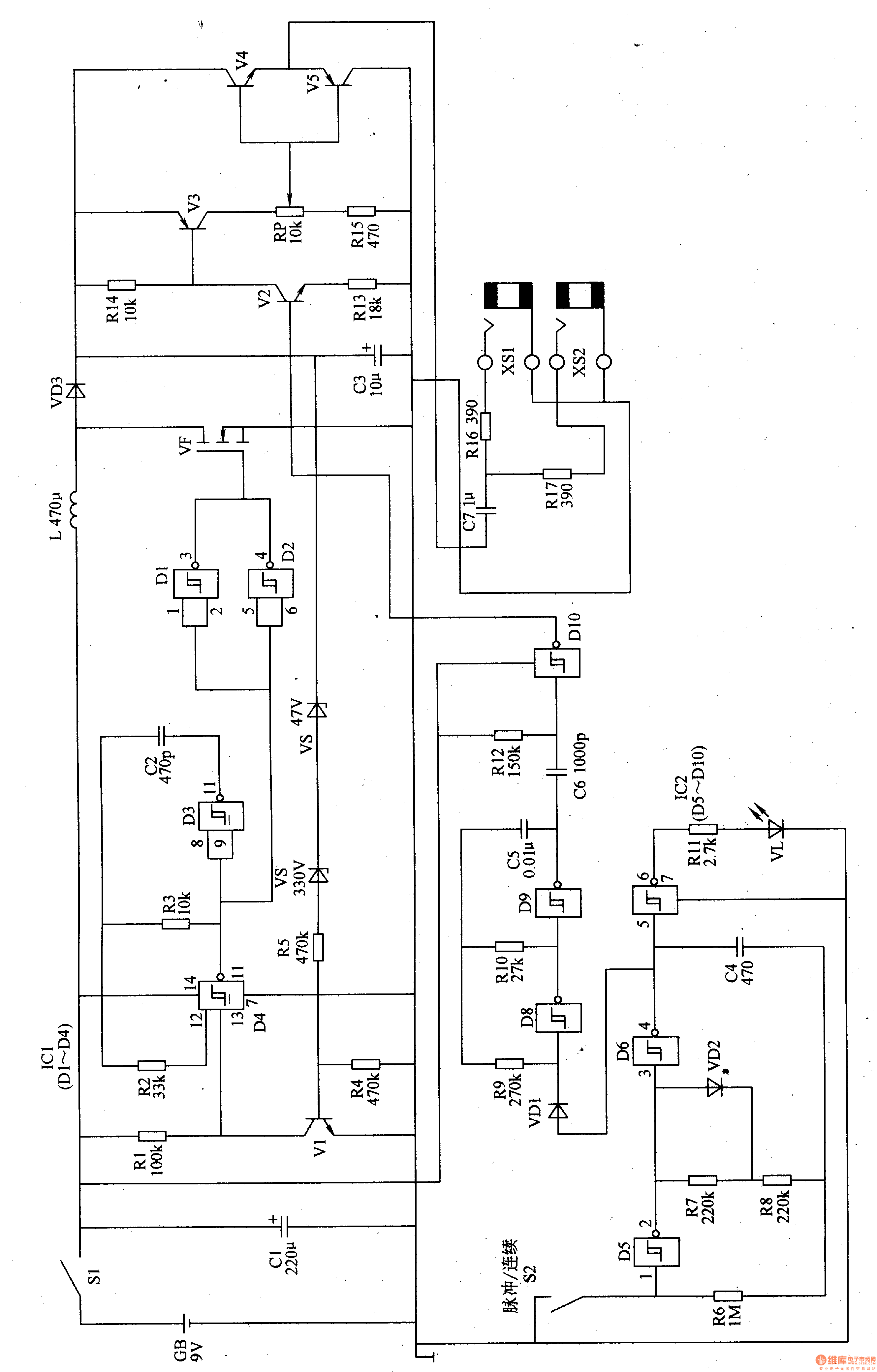
The high voltage generator circuit is composed of a Schmitt trigger integrated circuit ICl, an inductor L, a field effect transistor VF, a transistor V1, a Zener diode VS1, a VS2, a diode VD3, a capacitor C3, and related peripheral components. Among them, the flip-flop D3 and the flip-flop D4 inside lCl(Dl-D4) constitute a 65 kHz multivibrator; the flip-flop D1 and the flip-flop D2 form a buffer, which buffers and amplifies the oscillation signal; VF and L constitute a switching power supply. Circuit; VD3 and C3 form a rectifying and filtering circuit; Vl and R4, R5, VSl, VS2 form a voltage stabilizing circuit.
The pulse generator circuit is composed of a six-gate Schmitt trigger integrated circuit lCZ (DS-D10) and peripheral components. The low frequency oscillator is composed of the flip flop D8, the flip flop D9 and the peripheral RC element; the 2Hz ultra low frequency oscillator is composed of the flip flop D5, the flip flop D6 and the peripheral components; the working state indicating circuit is composed of the flip flop D7 and the light emitting diode VL The flip-flop D10 acts as a buffer amplifier.
The output circuit is composed of transistors V2-V5, output sockets XS1, XS2 and related RC components.
The function of the high voltage generator circuit is to provide 80V DC voltage to the output circuit. After the oscillation pulse of the 65 kHz multivibrator output is amplified by the buffer buffer, the control VF operates in the switching state (the state of alternately turning on and off). 80V DC voltage generated at both ends of C3 (when the voltage across C3 exceeds 80V, VSl and VS2 break through, make Vl turn on, 65kHz multivibrator stops vibration, C3 voltage drops), as output circuit Working power supply.
S2 is a "pulse/continuous" operating state selection switch. When S2 is turned on, the electronic analgesic device is in "continuous" working mode, the 2Hz ultra-low frequency oscillator does not work, VD1 is in the off state, the low frequency oscillator continuously outputs pulse signals, and its working frequency is about 12OHz; when S2 is disconnected, The electronic analgesic device is in the "pulse" mode, the 2Hz ultra-low frequency oscillator oscillates to modulate the low-frequency oscillator, and the low-frequency oscillator intermittently outputs a pulse signal whose operating frequency varies between 50-270 Hz.
The pulse signal outputted by the low-frequency oscillator is amplified by the DlO buffer and amplified by the transistor V2-V5, and a low-frequency pulse current is generated on the two external electrodes, and the pulsed current is used to stimulate the subcutaneous nerve of the human body to relieve the pain of the patient.
VL flashes in the pulse mode and continuously emits in the continuous mode.
Adjusting the resistance of the RP can change the pulse width of the output pulse current, thereby adjusting the stimulation level of the pulse current to the human body.
Component selection
Rl-R17 uses 1/4W carbon film resistor or metal film resistor.
The RP uses a small band switch (power switch Sl) to linearly synthesize a carbon film potentiometer.
Cl uses aluminum electrolytic capacitors with a withstand voltage of 16V; C2 and C6 select high-frequency ceramic capacitors; aluminum electrolytic capacitors with a withstand voltage of 160V have been selected; polyester capacitors or monolithic capacitors have been selected for C4 and C5; A CBB capacitor with a value of 160V.
VDl-VD3 selects 1N4148 type silicon switch diode for use.
VSl selects 1/2W, 33V silicon Zener diode; VS2 selects 1/2W, 47V silicon Zener diode.
VL uses φ3mm green LED.
Vl selects 3DGl80N or BClO0, 2N5058 type silicon NPN transistor; V2 and V4 select 2N5551 or 3DG84G type NPN transistor; V3 and V5 select 2N5401 or 3CA3F type silicon PNP transistor.
ICl selects CD4093 type four NAND gate Schmitt trigger integrated circuit; lC2 selects CD40106B type six non-gate Schmitt trigger integrated circuit.
L uses a small ferrite inductor.
S2 uses a small toggle switch.
GB uses 9V laminated battery.