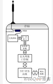
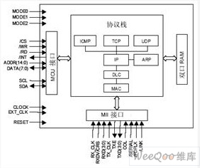
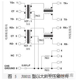
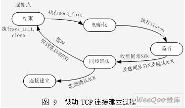
The basic research of underwater acoustic channel matching is an emerging research field based on hydroacoustics, marine physical acoustics and modern signal processing technology. The local sea acoustic channel measurement platform (Figure 1) constructed to meet the research needs can realize the systematic collection and real-time transmission of environmental information and channel parameters, and test the feasibility of the channel tolerance matching method. The buoy system plays an irreplaceable role in the research of underwater acoustic channels due to its flexibility, high efficiency and low self-interference. Most existing buoy systems use direct sequence spread spectrum radio stations to directly communicate on the surface. This method often does not use network protocols or use custom network protocols. The use of wireless bridges for water surface communication and TCP / IP as the network protocol will greatly enhance the networking of the buoy system. At the same time, since the TCP / IP protocol is one of the most mature network protocols, the stability and scalability of the buoy network have been improved, and it is even possible to directly control the buoy system through the Internet. Therefore, this article designs and implements a buoy network communication system based on the TCP / IP network protocol. 1.1 Buoy communication system based on TCP / IP network protocol The buoy used by the Institute of Underwater Acoustic Channel Matching has an underwater sensor unit, a signal processing unit and a water surface communication unit. Among them, the water surface communication unit is responsible for the exchange of information between the buoy and the shore-based control station, survey ship and other buoys, and requires network communication functions. The buoy network communication system is composed of a wireless network bridge, a TCP / IP protocol control unit and a microcontroller (MCU), as shown in Figure 2. The wireless bridge uses more mature bridge products, such as BreezeNET wireless bridge, whose function is to transmit TCP / IP data packets through the wireless network. The MCU is responsible for setting up the TCP / IP protocol stack, writing the data to be sent and reading the received data. The realization of TCP / IP protocol stack is the core part of buoy network communication system. The implementation method can be implemented by software, but this method generally requires a MCU with a high processing speed, and takes up a lot of code space. At the same time, programming needs to be very familiar with the mechanism and details of the entire TCP / IP protocol, which is difficult to develop. The hardware implementation method frees the MCU from the heavy network protocol operation, thereby improving the system efficiency. Data or commands are sent or received by the wireless bridge. It is connected to the 10Base-T general Ethernet interface controller RTL8201 through the RJ45 interface via a transformer. RTL8201 exchanges data with W3100A through MII standard interface. RTL8201 receives the Ethernet frame from W3100A, and then performs Manchester encoding. When sending an Ethernet frame, first add the frame start flag to the front of the frame. When an Ethernet frame exists in the network, the RTL8201 receiving module first synchronizes with the physical signal using a phase-locked loop circuit, then samples the physical signal and receives it, and sends it to the Manchester decoding function block. Finally, the W3100A can recognize the returned "0" "Code (the frame preamble has been separated), and sent to the network interface layer module through the MII interface. When sending data, the data is written into the W3100A's sending buffer by the MCU data interface. By controlling the relevant control registers of each protocol layer, the data is added to the TCP layer with various control flags, etc., and encapsulated into TCP segments to achieve reliable connection-oriented transmission ; The TCP segment is then handed over to the IP layer for packaging. An important function of the IP layer is to achieve fragmentation of the TCP segment, in order to achieve the purpose of using the data area of ​​the Ethernet frame with the maximum efficiency of the IP datagram. The complete IP datagram continues to be transmitted to the network interface layer. The LLC sublayer uses the unreliable bit link provided by the physical layer to achieve reliable packet transmission services. The MAC sublayer adds the physical address of the destination node to the data packet. The MAC implementation does not Reliable packet transmission. After passing through the network interface layer, it is finally encapsulated into a frame format, and then sent to the RTL8201 through the MII interface, where Manchester encoding and preamble signals are added in the RTL8201. When RTL8201 * finds that the physical link is idle, it immediately sends the data frame to the Ethernet through the RJ45 interface. When receiving data, the reverse operation is performed. The transceiver receives the physical signal on the Ethernet, separates the preamble and performs Manchester decoding, and transmits the result to the network interface layer. The MAC sublayer of the network interface layer checks whether the physical destination address of the frame is the same as its own. To determine whether to hand over to the LLC sublayer, LLC uses the error detection bit to determine whether the packet is correct. The correct packet is sent to the IP layer. In the IP layer, errors are detected, unpacked, and fragmented and reassembled, and then sent to the TCP layer. The TCP layer implements reliable connection-oriented transmission. Therefore, the TCP layer will perform strict error control, and then from Take out the data from the TCP segment, and then send it back to the MCU through the data interface. The physical frame is unpacked through each protocol layer, and finally the data is transferred back to the MCU. However, if the IP address or data is wrong when unpacking at each layer, the data packet will be discarded and retransmission is required. If the processed message is ICMP, UDP, or ARP, the general process is the same. The difference between different messages will be indicated in the corresponding packet header for protocol identification. 1.2 Introduction to TCP / IP protocol stack W3100A W3100A is a TCP / IP protocol stack chip, which includes TCP, IP Ver.4, UDP, ICMP, ARP and other Internet protocols and DLC, MAC Ethernet protocol. Its functional block diagram is shown in Figure 3. The W3100A chip is composed of 4 parts: a microcontroller interface unit, a network protocol engine, a dual-port RAM, and a network physical layer media switch interface MII (Media Independent Interface) unit. W3100A supports full-duplex 20Mbps data communication and can simultaneously support 4 independent network connections; provides 16KB of data buffered dual-port SRAM; adopts 0.35μm CMOS process, 64-pin LQFP package; uses 3.3V power supply voltage, which The I / O interface is compatible with 5V digital logic levels and can be easily connected to MCU and DSP interfaces. The main circuit of the system consists of microcontroller MSP430F169, network protocol stack W3100A, Ethernet interface controller RTL8201 and network interface. The connection between W3100A and MSP430F169 can adopt I2C interface mode or direct bus mode. The advantage of using the I2C interface mode is that the circuit is simple and takes up less port resources. However, the transmission speed of the I2C interface will be limited, so when a higher transmission speed is required, a direct bus interface can be used, as shown in Figure 4. W3100A provides MII interface to connect with RTL8201, in which pins RX_CLK, RXDV, RXD [0: 3] and COL are used for data reception, and TX_CLK, TXE, TXD [0: 3] are used for data transmission. In the realization of the interface, the Ethernet transformer is indispensable. On the differential transmit pin (TX + / TX-), a pulse transformer dedicated to 10BASE-T operation is required to send the data to be sent to the network. The data from the network also passes through the transformer and is received by the differential receiving pins (RX + / RX-). The function of the Ethernet transformer is mainly to separate the external lines from the RTL8201, to prevent interference and burn out the components, and to realize the live plug-in function. This design uses PULES J0011 transformer, its internal structure shown in Figure 5. The transformer integrates RJ-45 connector, which simplifies the connection and improves the reliability of high-frequency signal transmission. 3.1 MSP430 bus read and write W3100A has a dedicated microcontroller interface connected to the MCU, and its bus operation is similar to the MCU reading and writing to external memory. However, the MSP430 microcontroller does not have a special external expansion bus interface, so a general-purpose port is used here to simulate the external expansion bus port. The access to W3100A should be operated in accordance with its read and write timing, as shown in Figure 7 and Figure 8, the read and write program can be called as a function in the main program. Listed below are some read bus programs: The write bus process is similar to the read bus, except that the P4 port is set to the output state, and the write operation is valid (/ WE). It should be noted that the rising edge when / WE returns to high level triggers data writing. 3.2 Network transmission control Through the Socket API function specially provided by Wiznet for W3100A, the software design of network communication can be made more convenient. First initialize the W3100A's network settings, that is, set the default gateway, subnet mask, local physical address and IP address in the corresponding register, and then establish a Socket connection to achieve communication. The entire process is very similar to Windows Socket programming. The process of establishing a TCP connection is shown in Figure 9. First complete the chip's TCP / IP initialization, set the corresponding channel such as the 0 channel protocol selection register C0_SPOR to 0X01; select the TCP protocol, execute the sock_init command bit in the channel 0 command register C0_CR, and set C0_TW_PR, C0_TR_PR and C0_TA_PR to the same value ; Then execute the connect and listen command bits of C0_CR, at this time the TCP connection is established. The 16KB dual-port RAM inside W3100A is used as data transmission and reception buffer. The address space of 0x4000 ~ 0x5FFF is the sending data buffer, and the address space of 0x6000 ~ 0x7FFF is the receiving data buffer. The MCU program writes the data to be sent to the send buffer and reads the received data from the receive buffer. When sending batches of data, be sure to query the send data pointer once to calculate the size of the send buffer that can be used. Figure 10 illustrates the program flow of TCP data transmission. The process of receiving data is similar to the process of sending, and will not be repeated here. The key to functional testing is to experiment with the usability and stability of the system. To this end, a simplified communication network was established, using a PC as one terminal of the communication network and a buoy as another terminal. Experiment the function of this system by testing the communication between the two. First, test the network connection. As a necessary IP experiment, the PC sends the PING command to the buoy, and the PC displays the results as shown in Figure 11. In the case of a smooth local area network, the theoretical average response time of a 0-byte PING request is 1ms, and the experimental results verify that the network connection is normal. Test the stability of the system through a large number of data forwarding methods. The PC sends the data to the buoy, and the buoy forwards the data directly back to the PC. The PC compares the sent data with the received data to determine the error condition. Under the condition of room temperature, the communication distance is 100 meters, and three groups of transmission and reception experiments lasting 10 hours are carried out without packet loss. The bit error rate is <10-9, which meets the design requirements. It should be pointed out that due to different sea conditions and communication distances, the transmission error rate of the system will be different, but in most cases the system is completely reliable as a channel for command transmission and reception. The application of TCP / IP protocol in the buoy system greatly enhances the stability and scalability of the buoy network. This design uses the MSP430 microcontroller and the network protocol stack W3100A to realize the low-power network communication system of the buoy system, which provides an ideal network communication guarantee for the basic research of underwater acoustic channel matching. At the same time, this design can also be embedded in other equipment, such as field measuring instruments, vehicle-mounted systems, etc., to provide network services for more embedded systems, and has a very broad prospect. Auto Identify Technology - The LENCENT multi usb plug charger would identify the connected devices intelligently and provide optimized charging universal compatibility. It`s suitable with electronic devices and models, from iPhones, Samsungs, HTC Nexus, Mp3 Players, Bluetooth Speaker Headsets to iPads and Power Devices Iphone Travel Charger Europe,Travel Charger Best,Travel Charger Dual Usb,Usb Travel Charger Dongguan City Leya Electronic Technology Co. Ltd , https://www.dgleya.com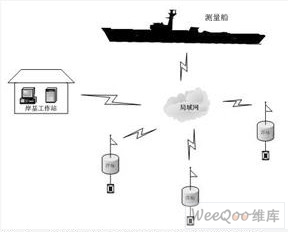

At the same time, it should be noted that when designing the reset circuit, since the reset pin of W3100A is active high, and the reset pins of MSP430F169 and RTL8021 are active low, it is required to generate both high and low resets when designing the reset circuit The signal is shown in Figure 6. 


High Speed Charging - Each port could offer maximum current up to 4.4A, fast-charging for any connected device efficiently, definitely you can charge 4 devices at the same time
Certified Safe - The certifications of EMC/LVD/ROHS make this travel plug a safety system with which would automatically stop charging once the devices are fully charged, or overheat, over-load, or short circuit
★Ideal for Travel - Portable Sized USB plug adapter with Interchangeable UK/USA/EU/AUS plugs and international voltage compatibility, makes it easy for multiple devices charging, anywhere you go (apply for type A / C / E / F / G / I )
Design Strategy of Buoy Network Communication System Based on TCP / IP
Design Strategy of Buoy Network Communication System Based on TCP / IP