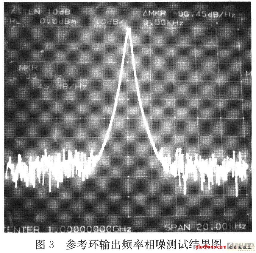
0 Preface The portable field strength tester requires high phase noise of the first local oscillator, and its reference frequency is provided by the reference loop, so the phase noise of the reference loop is also very high. The reference loop uses sigma-delta modulation technology to reduce phase noise. See the reference for specific principles. 1 Design plan The main performance indicators of the first local oscillator of the portable field strength meter: Frequency range: 4031.25 ~ 7031.25MHz; single-sideband phase noise: ≤ï¼100dBc / Hz @ 10kHz Calculate the index of the reference frequency from this: Frequency range: 31.25 ~ 62.5MHz; single-sideband phase noise: ≤ï¼118dBc / Hz @ 10kHz The block diagram of the first LO scheme is shown in Figure 1. In Figure 1, the left frame is the local oscillator ring; the right frame is the reference ring; the rest is the step ring. 2 Reference loop filter bandwidth design The phase noise in the bandwidth of the PLL loop is mainly determined by the noise of the frequency divider, phase discriminator and reference signal, while the phase noise outside the loop band is determined by the phase noise of the VCO. Therefore, when selecting the bandwidth, the phase noise in the bandwidth and the phase noise of the VCO should be comprehensively considered to achieve the best noise effect. The loop filter bandwidth of the reference loop is calculated as follows: The loop filter of the reference loop uses an active second-order integral filter. Normalized phase noise power spectral density of voltage controlled oscillator: Where: f0 is the center frequency of the voltage-controlled oscillator; F is the frequency deviation; Q is the loop quality factor. The normalized phase noise power spectral density of the crystal oscillator: Where: fr is the resonance frequency of the crystal oscillator; F is the frequency deviation. Under the condition of ignoring the noise of the phase detector itself, the normalized total phase noise power spectral density of the loop output is: The second-order phase-locked loop system is usually designed to be used in an under-damped state, ie 0 "ξ" 1. Now take the damping coefficient ξ = 0.5, fr = 10MHz, f0 = 500MHz, Q = 500, then: From this, the loop closed-loop frequency response is calculated will Therefore, the reference loop integral filter bandwidth is selected to be 104 Hz, so that the phase noise of the output signal is minimized. 3 Increase the output frequency In the actual circuit, the reference signal can be obtained by raising the output frequency of the reference loop to 500MHz-1000MHz and then dividing by 16. The near-end phase noise of the reference frequency of the local oscillator loop can be improved by 20 & TImes; The phase noise of the frequency only needs to reach -94 dBc / Hz @ 10kHz to meet the index requirements. The single-sideband phase noise of the output signal in the actual test is -96dBc: / Hz @ 10kHz, which fully meets the index requirements. The reference loop improves the near-end phase noise of the reference signal of the local oscillator ring by increasing the output frequency and then dividing the frequency, thereby improving the near-end phase noise of the first local oscillator. 4 Test results After the loop is locked, use a spectrum analyzer to test the phase noise at a frequency of 1GHz. The result is -96dBc / Hz @ 10kHz, which meets the requirements of the first local oscillator phase noise. The experimental results are shown in Figure 3: 5 Conclusion This article mainly introduces the low-noise design of the first local oscillator reference loop of the field strength instrument. Now the instrument has started mass production. Due to the limitation of the author's level, mistakes in the article are inevitable, and please correct me a lot.
In this range,including Rotary Switch,Door Switch , Push Button Switch, 303 Cord-Line Switch and so on.
Rotary Switch is mostly used in the cooler area,according to different requirement,many function can be met.For example,4 Position,6 Position,3 Position etc.
High Quality and Reseasonal Price,it is very popular.
Push Switch,Toggle Switches,Led Push Switch,Push Button Switch Ningbo Kara Electronic Co.,Ltd. , https://www.kara-switch.com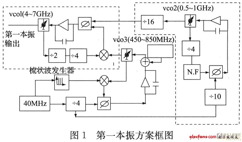


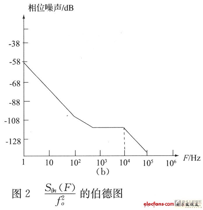
 The Bode diagram is shown in Figure 2.
  Drawing together in Figure 2 (a), it can be seen that the two noise spectra intersect near F = 104Hz. Considering comprehensively, it is obviously most advantageous to choose the frequency where the two spectral lines intersect, that is fn = 104Hz. The phase noise after filtering is shown in the dashed line in Figure 2 (a). It can be seen from the figure that after the low-pass filtering of the crystal oscillator noise, the noise spectrum in the high frequency band of F》 fn is already lower than that of the crystal oscillator. Figure 2 (a) is the normalized output phase noise. The actual output phase noise should be multiplied by fo2, as shown in Figure 2 (b).
 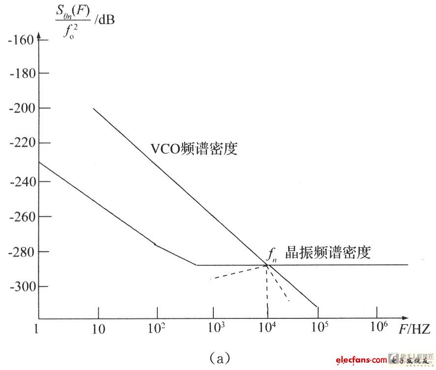 [Next]