Overview: 1 Working principle of full-bridge transformer switching power supply The working principle of full-bridge transformer switching power supply is very similar to that of push-pull transformer switching power supply and half-bridge transformer switching power supply. Let me first understand the full-bridge transformer switch. How the power works. Figure 1 below shows the working principle of the full-bridge transformer switching power supply. In the figure, K1, K2, K3, and K4 are four control switches, which are divided into two groups; K1 and K4 are one group, and K2 and K3 are another group. When the switching power supply is working, one group is always connected, the other group is turned off, two sets of control switches alternately work in turn; T is a switching transformer, N1 is the primary coil of the transformer, N2 is the secondary coil of the transformer; Ui is DC Input voltage, R is the load resistance; uo is the output voltage, and io is the current flowing through the load. The Embedded Printer does not need carbon ink or thermal technology, and only needs thermal paper roll to print all kinds of content. It is an economical and fast printing. Embedded printer supports the secondary development of major systems. There are two types of manual tearing and automatic cutting. It is also suitable for various terminal equipment, such as medical testing equipment, intelligent classification equipment, industrial testing equipment, intelligent vehicle-mounted printing list equipment, etc. At the same time, it also supports the secondary development of MCU, Android, Raspberry Pi, windows and other systems. Testing Instrument Embedded Printer,Micro Embedded Printer,Usb Serial Printer Shenzhen Geyi Technology Co., Ltd. , https://www.gy-printer.cn
The full-bridge transformer switching power supply also belongs to the double-excited transformer switching power supply. It also has the high voltage utilization rate of the push-pull transformer switching power supply, and has the high voltage resistance of the half-bridge transformer switching power supply. Since the full-bridge transformer switching power supply is often used in applications with high operating voltage and high output power, this paper is mainly based on the design of full-bridge transformer switching power supply. 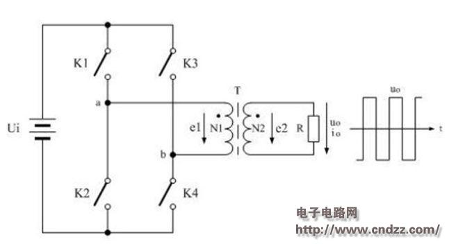
As can be seen from the above schematic diagram, the control switches K1 and K4 and the control switches K2 and K3 form exactly the arms of one bridge, and the transformer is bridged as a load in the middle of the arms of the bridge. Therefore, we refer to the circuit of Figure 1 as a full-bridge switching power supply circuit. In the figure, when the control switches K1 and K4 are turned on, the power supply voltage Ui is applied to both ends a and b of the winding of the transformer primary winding N1, and at the same time, due to the electromagnetic induction, the ends of the winding of the secondary winding N2 of the transformer are also A voltage proportional to the input voltage Ui of the N1 winding is output and applied to both ends of the load R to cause the switching power supply to output a positive half cycle voltage.
When the control switch control switches K1 and K4 are turned from on to off, the control switches K2 and K3 are turned from off to on, and the power supply voltage Ui is applied to the ends b and a of the winding of the transformer primary winding N1; Similarly, due to the electromagnetic induction, a voltage proportional to the input voltage of the N1 winding is also outputted at both ends of the winding of the secondary winding of the transformer N2, and is applied to both ends of the load R, so that the switching power supply outputs a negative half-cycle voltage.
When the control switches K1 and K4 are turned on, the power supply voltage Ui is applied to both ends a and b of the winding of the transformer primary winding N1, and a current will pass through the winding of the primary winding N1 of the transformer, which is generated in the core of the transformer by electromagnetic induction. The magnetic field generates a magnetic field line; at the same time, a self-induced electromotive force e1 is generated at both ends of the winding of the primary winding N1, and an induced electromotive force e2 is also generated at both ends of the winding of the secondary winding N2; the induced electromotive force e2 acts on both ends of the load R, Thereby generating a load current.
(Please read the PDF for details)