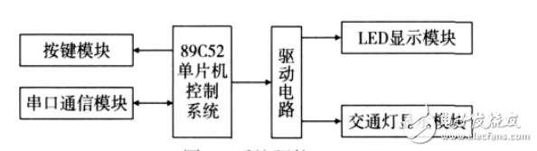
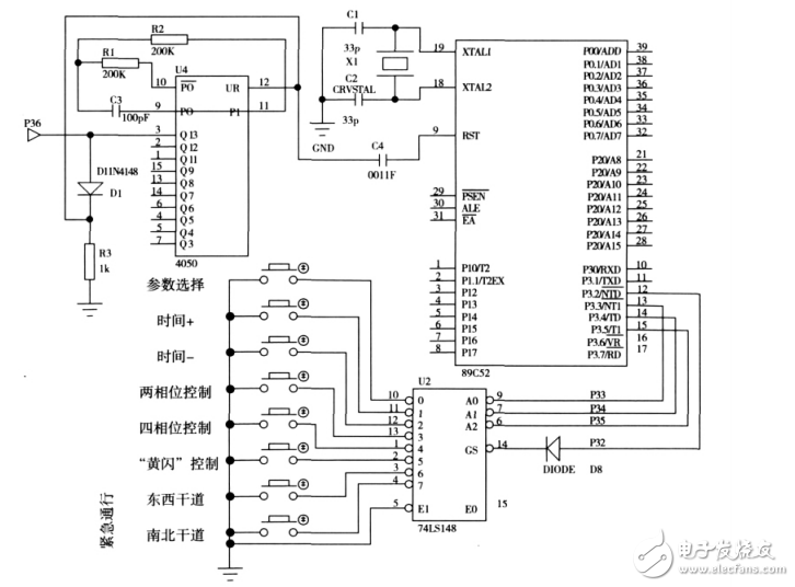
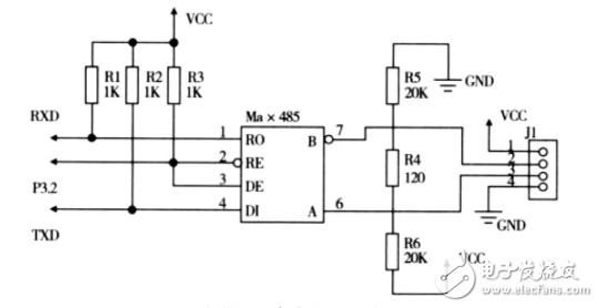
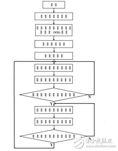
The traffic light control system introduced in this paper has certain advantages compared with the current general traffic light control system in China, which is embodied in the following aspects: 1) Control parameters can be flexibly adjusted. At present, most of the urban intersections use fixed-cycle control. Once the period and the green-tone ratio are selected, they will not change. This may cause the traffic signal control signal to be unsuitable for the actual traffic flow. Therefore, only the control parameters such as cycle, red time, and green time can be adjusted according to the actual situation of traffic flow, so as to better control the traffic at the intersection, reduce vehicle delay and improve the traffic capacity of the intersection. 2) The phase can be changed. For an actual intersection, the two-phase control traffic flow is simple and efficient, but there are more conflict points and lower security. The 4 phase eliminates the conflict caused by the left-turning vehicle, and the safety is very high. However, in the case of small traffic flow, the traffic efficiency is low. Therefore, if the phase change can be performed according to the magnitude of the traffic flow and the steering ratio of the vehicle, Traffic at the intersection will be more orderly and the control effect will be better. 3) Emergency vehicle traffic control. When an emergency vehicle performs an emergency mission through an intersection, regardless of the timing of the original traffic light, the two lanes should be banned and the emergency vehicle passed. Emergency access control can be achieved through the emergency access button. 4) "Yellow flash" control. In the case of less traffic and less traffic at night, especially at midnight, a "yellow flash" control can be performed on the traffic signal to improve access efficiency and reduce unnecessary waiting time. At this point, the traffic light changes from the original multi-phase to a single yellow light. The system is mainly composed of single-chip control system, button module, serial communication module, LED display module, traffic light display module, etc., as shown in Figure 1. Among them, the single-chip computer system is the main controller of the system, which is used to control the coordination of other modules; the button module adopts the external interrupt INT0 mode; the serial communication module adopts the RS-485 interface; the LED display module is used to display the traffic light control parameters; The display module is used to display the traffic conditions of each lane. Figure 1 system hardware This system uses AT89C52 chip as the core control device. Its P0 and P2 ports are used for digital tube display control, P1 port is used for traffic light display control, and key processing is mainly performed by interrupt mode, especially the “watchdog†circuit is added to ensure the stability of the system. The basic peripheral circuit of the single chip microcomputer is shown in Figure 2. The button control module is controlled by the P3 port of the AT89C52 chip, and the circuit is shown in Figure 2. When a key is pressed, the generated negative pulse is interrupted by the GS of the encoder 74LS148, and the microcontroller responds to the interrupt and reads the encoded information of the 74LS148, thereby performing corresponding processing according to pressing different keys. Figure 2 MCU basic circuit and button control circuit The LED display module includes a control parameter adjustment display module and an intersection countdown display module 2, and the 8-part LEDs of the two parts adopt a dynamic display mode, that is, the corresponding segments of the segment lines of all the digital tubes are connected in parallel, and are connected to the P0 port. Each LED is controlled by the P2 port to achieve timing gating of the LED. The traffic light display module is controlled by the P1 port of the single-chip microcomputer. The 32 traffic lights are used to simulate the traffic lights of the intersection (the straight green light, the left turn green light, the red light and the yellow light in the four directions of the intersection), and the sidewalks of each intersection. Traffic lights. In this module, the RS-485 interface is used to complete the communication between the host computer or the adjacent traffic light control system and the single-chip microcomputer, thereby realizing the control, debugging and alarm of the system. RS-485 interface has good anti-noise interference, long transmission distance and multi-station capability. The serial port circuit diagram is shown in Figure 3. Figure 3 serial port circuit The main program flow chart is shown in Figure 4. The program mainly completes the initialization of the traffic control parameters, the trigger mode of the interrupt, the initialization of the timer T0, the opening and opening timers, the control of the signal phase state, and then cyclically calls the display subroutine to realize the control of the traffic light. . Figure 4 main program flow
With the development of the times, the consumption level of people is gradually increasing. At the same time, people's entertainment methods are beginning to diversify, especially for modern young people. As a result, different kinds of electronic products are starting to be in people's lives, and the booming Electronic Cigarette industry reflects this.
Described including the upper shell, the upper shell at the top of the smoke outlet, as described in the bottom of the upper shell with airway, described with the smoke outlet in the airway and also to match the upper shell, the lower part of the shell described the airway in the direction of the lower shell extension, as described in the lower shell near one end of the upper shell is equipped with oil mouth, described the lower shell with batteries, described at the bottom of the bottom shell has come in The air port is provided with an oil storage bin in the lower shell, and the air passage passes through the oil storage bin and is provided with a heating atomization bin at one end away from the smoke outlet. The utility model has beneficial effects: it can meet the smoking habit of different users, avoid the premature end of the use experience caused by excessive consumption of smoke oil, and indirectly prolong the service time and life of the product.
Refillable E-Cig Oem,Refillable Vape Pod,Refillable Vape Pen Oem,Refillable Mod Oem Shenzhen MASON VAP Technology Co., Ltd. , https://www.e-cigarettefactory.com