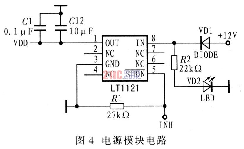
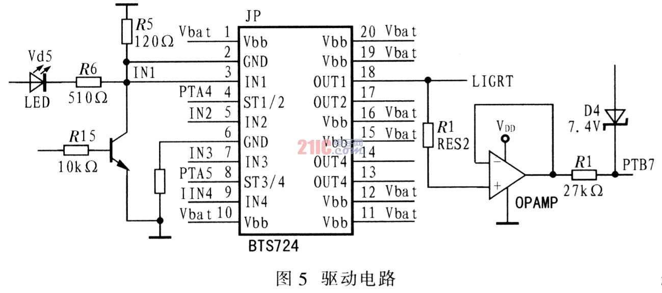
This article refers to the address: http:// 2.2 Device Introduction The basic LIN node circuit mainly includes MCU, LIN transceiver, power module and lamp driving circuit. 2.2.2 LIN transceiver selects TJAl020 as LIN transceiver. TJAl020 is the interface between LIN master/slave protocol controller and LIN physical bus. It is mainly used as vehicle sub-network. Its baud rate is 2.4 to 20 Kb/s. The transmit data stream input by the controller at the TXD pin is converted to a LIN bus signal by the LIN transceiver, and the slew rate and waveform are controlled by the transceiver to reduce extremely low electromagnetic emissions (EME). The output pin of the LIN bus is pulled high by an internal termination resistor. The transceiver detects the data stream on the input pin of the LIN bus and sends it to the microcontroller via pin RXD. The main features of TJAl020 are: 2.2.3 Power Module In this design, the voltage regulator of the LIN module uses the micro power consumption and low dropout regulator LT11l-5. By using LT125-1 to input low level to SHDN, it can enter the stop mode. At this time, the quiescent current is only 16μA, so when there is no activity on the bus, the power consumption can be reduced. In addition, the device also prevents The reverse function of the input and output powers prevents reverse current flow even if the output does not add a diode. Figure 4 shows the power module circuit. 2.2.4 The driving circuit of the lamp uses the power driver BTS724G to drive 2l W and 5 W lights. The driver is an N-channel MOSFET power tube designed by Infineon. It integrates a charge pump, current drive, and has a fault feedback function that detects load current (including overload, over temperature, and short circuit). The BTS724G is controlled by 12 V or 24 V load and is suitable for a variety of resistive, inductive or capacitive loads. It is especially suitable for loads with high inrush current such as lights, and can be used as an alternative control method for relays and fuses. BTS724G also has many protection functions such as short circuit protection, overload protection, over voltage protection, over temperature shutdown, ground loss and power failure protection, electrostatic discharge protection and power reverse protection. Figure 5 shows the drive circuit. 3 software design The lamp control system mainly completes two functions: one is to realize the control of the LED sub-node to the lamp; the other is to realize the diagnosis of the lamp failure. In the control, the system determines whether the system has failed by analyzing the potential of the bus potential and the input, output, and fault diagnosis pins in the drive circuit. 4 Conclusion The LIN bus-based online diagnostic system for headlights is introduced and the hardware module and software architecture are analyzed briefly. The LIN bus system has the characteristics of simple structure, reliable performance and low price, and is an inevitable trend in the development of automotive electronic technology. At present, how to adopt bus technology in China to improve vehicle performance and reduce manufacturing and maintenance costs has become a hot spot for auto manufacturers.
Automotive bus technology is one of the applications of fieldbus, and the fieldbus was originally used only for industrial control. The so-called field bus is a kind of bus topology network applied at the bottom of production. The problem to be solved by the car body control network is to establish a unified low-cost low-end communication network standard. LIN exists as an auxiliary bus of CAN, realizes the layering of the body control network, and realizes the body control network at a lower cost. The goal of the LIN bus is to locate low-end communication between the nodes of the body network module. Compared with CAN, LIN uses low-cost hardware slave nodes, which reduces the cost of the hardware platform. In addition, LIN can meet the transmission rate requirements of most low-end application objects. Therefore, UN realizes network communication between switching devices at a lower cost, effectively supporting the control of distributed mechatronic nodes in automotive applications.
2 hardware circuit design
2.1 System design ideas
   The LIN slave node processes the control signals sent by the node and measures the state of the lamp driver circuit. After receiving the message information from the node, the corresponding control signal is sent to the vehicle lamp, and the state of each lamp is analyzed. If a failure occurs, a data message is generated and sent to the total node. After detecting the signal sent by the total node, the LIN slave node first identifies through the message frame to see if it belongs to its own message information. If it belongs, it first determines whether the message is the query information, and if so, returns a response message. If it is the control information, it controls the corresponding lamp and measures the potential of the measurement point on the lamp driving circuit. Process it. See if it has failed. If a fault occurs, the information is sent to the total node via the LIN bus. Figure 1 shows the hardware circuit design of the LIN node. 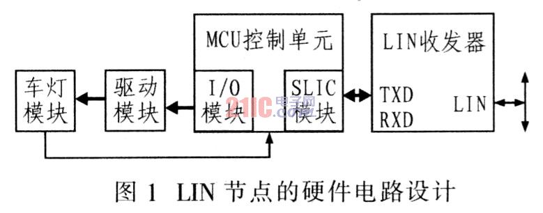
2.2.1 MCU control unit design MCU selects MC68HC908QL4. It integrates a slave interface control module SLIC (Slave LIN Interface Controller), in general, SUC can be used as an SCI port. The main features of the device are:
Has an independent LIN message identifier, 8 B message buffer area;
Automatically adjust the baud rate, frame synchronization;
Automatically process and correct UN sync interval (SYNCH BREAK) and sync field (SYNCH BYTE);
The LIN message without error generates up to two interrupts;
Complete LIN error detection and reporting;
High-speed LIN reaches 83.33 Kb/s~120 Kb/s;
Enhanced detection and its generation including ID.
As long as the corresponding registers are set according to the needs of the module, data can be automatically transmitted and sent according to the LIN bus protocol. This reduces the difficulty of software development compared to the SLIC module's microcontroller. The connection of the MCU module is shown in Figure 2. 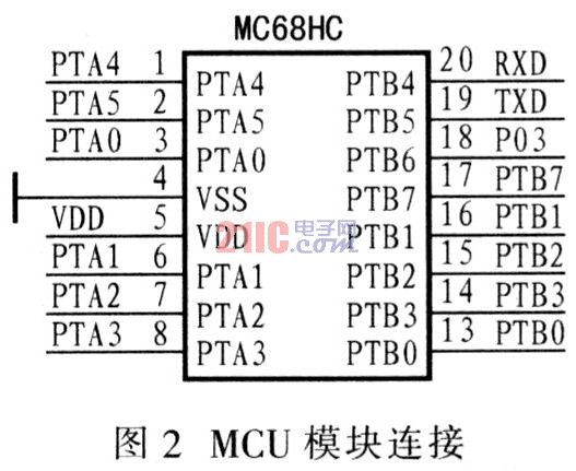
Has a baud rate of up to 20Kb/s and extremely low electromagnetic emissions (EME);
High immunity to electromagnetic interference (EMI) and low slope mode can further reduce EME;
Have a wake-up source to identify local or remote;
Has very low current consumption in sleep mode, enabling local or remote wake-up;
Has a send data timeout function;
Short circuit protection of battery and ground by LIN bus;
It has bus terminals and battery pins to prevent transients in the automotive environment.
Figure 3 shows the LIN module circuit design. 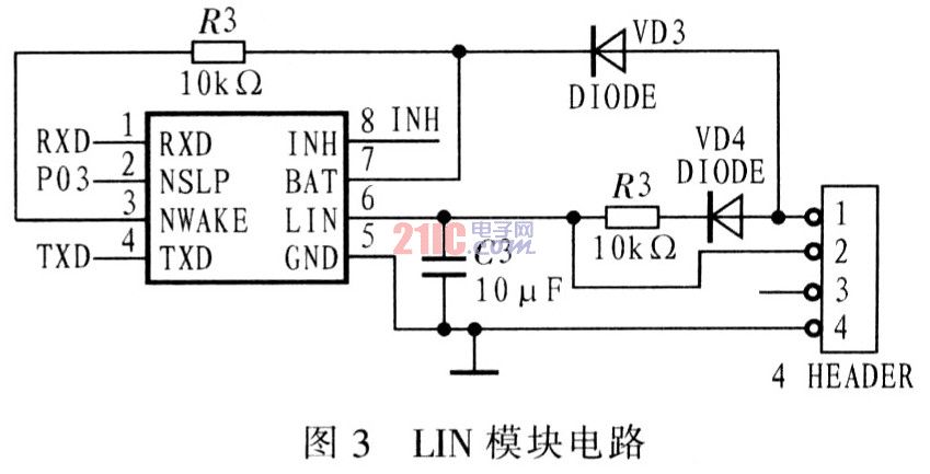
Software design is key to enabling LIN bus nodes to perform communication tasks efficiently and in real time. The use of structured programming has better modularity, portability and modifiability.
The LIN information is received by the interrupt mode. When the MC68HC90-8Q14 controller detects the information frame that meets the requirements of the node, it first determines what information frame is received by the local node, and if it is control information, it receives 2 bytes of data. Information; if it is query information, the state of the local node headlights is sent back to the master node in the form of an information frame to reflect the node condition. It is then determined that if the data frame is received, the corresponding information is read on the data register (SLCDx) in the SLIC module. Finally, according to the relevant bits in the data information, the vehicle lamp control is performed. After the control signal is sent, the potentials of the input, output and fault diagnosis pins of the lamp driving chip are collected correspondingly, and the fault is judged by the analysis of the potential, and if the fault occurs, Then send a fault message. Figure 6 shows the program flow chart. 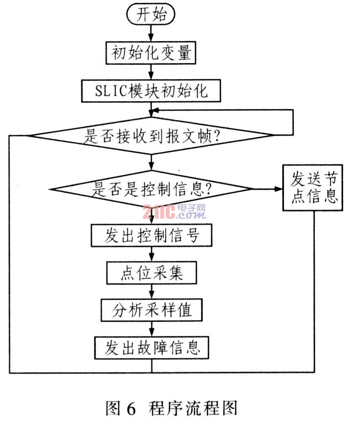
Design and Implementation of Online Diagnosis System for Car Light Based on LIN Bus
1 Introduction