This article refers to the address: http://
In recent years, voice systems have been widely used in embedded digital audio products. In consumer electronic products such as MP3s and mobile phones, the requirements for these personal terminals have long been limited to simple calls and simple word processing. High-quality sound is currently An important trend in development. With the improvement of the performance of embedded systems, it is possible to decode and play various music formats in ARM embedded systems. Driven by the demand for voice functions, more and more manufacturers have introduced voice processing interface protocols with various functions and standards. The IIS (Integrate Interface of Sound) bus is a serial digital audio bus protocol proposed by Philips. It is a multimedia-oriented audio bus dedicated to data transfer between audio devices, providing a sequence of digital stereo connections to standard codecs. The IIS bus processes sound data. Other signals, such as control signals, must be transmitted separately. The IIS bus typically has four signal lines, including serial data input (IISDI), serial data output (IISD0), left/right channel selection (IISLRCK), and serial data clock (IISCLK). The ISL2RCK and IISCLK are generated. Master device.
The hardware part of the entire audio system is mainly the connection and implementation of CPU and CODEC. Philips has produced an audio codec chip UDAl341TS that supports the IIS bus data format. It uses bit stream conversion technology for signal processing, completes analog-to-digital conversion of sound signals, and has a programmable gain amplifier and digital automatic gain controller due to its Powerful, low power, low voltage and DSP voice capabilities, it has been widely used in a variety of embedded voice systems. At the same time, the author's patent license for utility models for touch-based voice menu systems is under review. This paper first introduces the IIS bus interface in S3C2410X, and introduces the software and hardware interface implementation method of UDAl341TS voice chip in touch voice electronic menu system.
1 IIS bus interface in S3C2410X The IIS bus interface provided by S3C2410X can be connected to an external 8/16-bit stereo sound decoding code IC as a codec interface to realize a micro-recording and portable application. It supports IIS and MSBjustifled data formats. The IIS bus interface provides a DMA transfer mode for FIFO queue access instead of interrupts. It can send and receive data at the same time, or it can only send or receive data.
1.1 IIS bus features (1) 1 channel DMA-based IIS bus for audio interfaces;
(2) 8/16 bits of serial data transmission per channel;
(3) 128 B FIFO is used for transmission/reception;
(4) Support IIS format and MSB verification data format.
1.2 Data Transfer Mode The built-in IIS bus interface of the ARM chip can read the data on the IIS bus, and can also provide DMA transfer for the FIFO data, so as to transmit and receive data at the same time.
The IIS interface of the S3C2410X has three data transmission methods:
(1) Normal transmission mode: The normal transmission mode is based on the FIFO register. The CPU accesses the FIFO register by polling mode and controls the FIFO through the 7th bit of the IISCON register. If the FIFO is full, the 7th bit of IISCON is set to “Oâ€, indicating that data cannot be transferred; otherwise, the 7th bit of the FIFO is set to “1â€, indicating that data can continue to be transmitted.
(2) DMA mode: This mode is an external device control mode. By setting the ISFCON register, the IIS interface can work in this mode. It uses the means of stealing bus control to exchange data between external devices and RAM, thereby increasing the throughput of the system. There are four channels of DMA controllers in the S3C2410X chip for controlling various external devices. IIS shares two bridged DMA (BDMA) type channels with other serial peripherals.
(3) Transmission/reception mode: In this mode, IIS data simultaneously receives and transmits audio data through two-channel DMA.
1.3 Signal Line Signal Lines Total 5:
(1) Serial data input (IISDI);
(2) Serial data output (IISDO);
(3) Left/Right channel selection (IISLRCK);
(4) Serial data clock (IISCLK);
(5) Audio system main clock CODECLK.
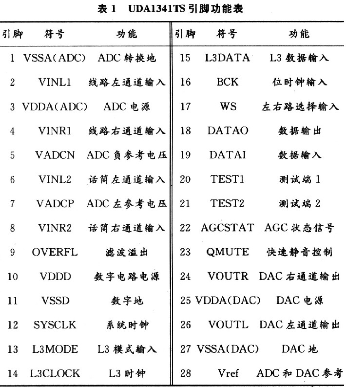
2 Introduction to UD 's voice control chip UDAl341TS UDAl341TS is an economical audio CODEC from Philips for analog audio signal acquisition (audio AD) and digital audio signal analog output (DA), and through IIS digital audio Interface for digital processing of audio signals. With 3 V low voltage, low power consumption, high fidelity, wide dynamic range and low distortion, the high quality features are widely used in home pocket multimedia stereo equipment, notebook computers, digital video cameras and computer audio signal processing equipment. Its pin diagram is shown in Figure 1, and its pin functions are shown in Table 1. 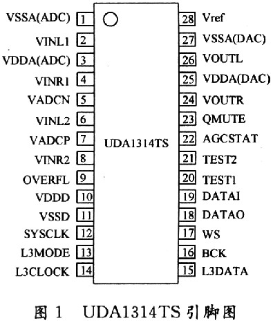
2.1 Main characteristics of UDAl341TS The main features of UDAl341TS are as follows:
(1) Low power consumption;
(2) a supply voltage of 3.0 V;
(3) a system clock of 256, 384, 512 times the sampling frequency;
(4) All inherited analog front ends containing AGC;
(5) ADC adds an integrated analog front end;
(6) The ADC supports 2 V (RMS value) input signal;
(7) having a detector for simple voltage overload;
(8) Independent power control ADC and DAC;
(9) The DAC does not have to have a backend filter;
(10) Its functions can be managed via the L3 bus.
2.2 Working mode The dual channel stereo analog to digital conversion controller has four working modes:
(1) ADCl input channel 1 working mode (for line input), input channel 2 is closed;
(2) ADC2 input channel 2 working mode (microphone input), input channel 1 is off, with PGA and AGC control characteristics;
(3) ADCl+ADC2 mixed working mode with PGA and AGC control characteristics;
(4) ADC1-ADC2 mixed working mode.
2.3 L3 control characteristics The microprocessor and UDAl341TS chip L3 interface, complete the following control functions: power control; chip reset; digital mode, analog-to-digital conversion gain switch; digital mode, analog-to-digital conversion polarity control; double speed recording Control; volume, high and low, mute control; microphone sensitivity control; programmable gain amplifier control, digital AGC automatic gain control.
The channel 2 of the UDAl341TS constitutes a programmable gain-amplified front dual-channel stereo analog-to-digital conversion control circuit, programmable gain amplifier (PGA), and the PGA is set through the L3 interface. The gain can be set to: -3 dB, 0 dB, 3 dB, 9 dB, 15 dB, 21 dB or 27 dB, Channel 2 also features digital automatic gain control AGC with a digital automatic gain control (AGC) range of 60.5 dB and a control step of 0.5 dB. Input channel 1 has a gain of 0 or 6 dB amplification and is controlled via the L3 interface. In this way, the input signal can reach 1 V or 2 V.
3 UDAl341TS application in S3C2410X based touch voice menu system
3.1 Hardware Connection Scheme The connection between the voice driver chip UDAl341TS and the microcontroller S3C2410X is shown in Figure 2. 
The IIS bus signal of the S3C2410X is directly connected to the IIS signal of the UDAl341TS. The L3 interface pins L3CLOCK, L3MODE and L3DATA are connected to the GPB1, GPB2 and GPB3 general data output pins of the S3C2410X, respectively. The UDAl341TS provides two sets of audio signal input interfaces, each of which includes two channels on the left and right.
Since the IIS bus only processes audio data, the UDAl341TS also has an L3 bus interface for transmitting control signals. The L3 interface is equivalent to the mixer control interface and can control the bass and volume of the input/output audio signals. The L3 interface is connected to the three general-purpose GPIO input/output pins of the S3C2410X. These three I/O ports are used to simulate the entire timing and protocol of the L3 bus. It must be noted here that the clock of the L3 bus is not a continuous clock. It only sends out a clock signal of 8 cycles when there is data on the data line. In other cases, the clock line always remains high.
3.2 Software Design Solution The digital voice module IIS can realize the functions of recording, playback and loop playback after proper configuration. Because the audio data transmission is relatively simple, this paper mainly introduces the flow chart of the software design. The flow chart is shown in Figure 3. 
4 Conclusion The application of UDAl341TS in the touch-based voice electronic menu system based on Samsung S3C2410X microprocessor is introduced. The system has been implemented on the development platform based on S3C2410X, which can smoothly collect and play audio, and has achieved good results.
Application of UDAl341TS in touch voice electronic menu system
O Introduction