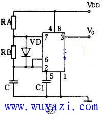
To generate a square wave output using a 555 oscillator circuit, the configuration shown in Figure 9 can be employed. This circuit builds upon the design in Figure 8 by adding a diode VD in parallel with resistor RB. When RA equals RB, the charging and discharging time constants of the capacitor C become equal, resulting in a symmetrical square wave output. The frequency of this square wave is given by the formula: f = 0.722 / (RAC), where RA equals RB. The use of a diode in this setup allows for greater flexibility in adjusting the duty cycle of the pulse waveform. By controlling the charging and discharging paths through the diode, it becomes possible to fine-tune the output signal to meet specific application requirements. Building on this basic configuration, potentiometers are often added to the RA and RB resistors to allow for variable control over the oscillation frequency and duty cycle. Additionally, multiple 555 timer circuits can be connected in series or parallel to create more complex waveforms or expand the range of frequencies. These circuits are commonly used as AC sources, capable of producing signals from just a few hertz up to several megahertz. Due to their simplicity, reliability, and ease of implementation, 555-based oscillator circuits remain one of the most popular choices in both educational and industrial applications. Whether you're designing a simple timing circuit or a more advanced signal generator, the 555 timer continues to be a versatile and essential component in electronics. Three Phase High Frequency Tower UPS Three Phase Tower Online UPS,Tower Online UPS,High Frequency Tower Online UPS Shenzhen Unitronic Power System Co., Ltd , https://www.unitronicpower.com