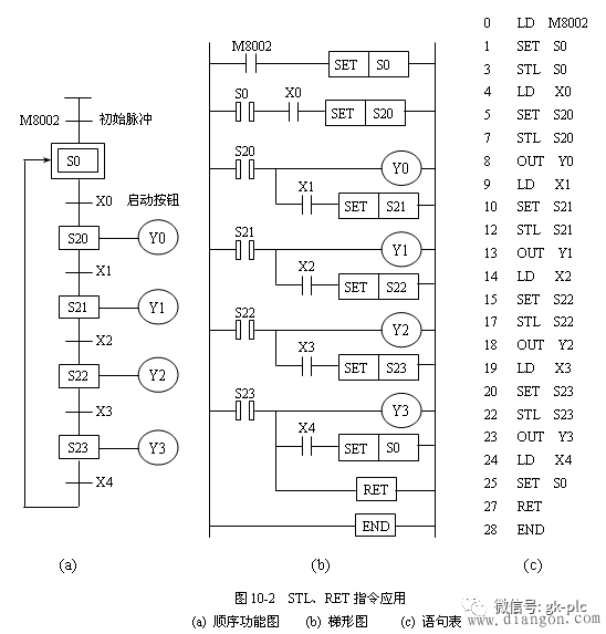
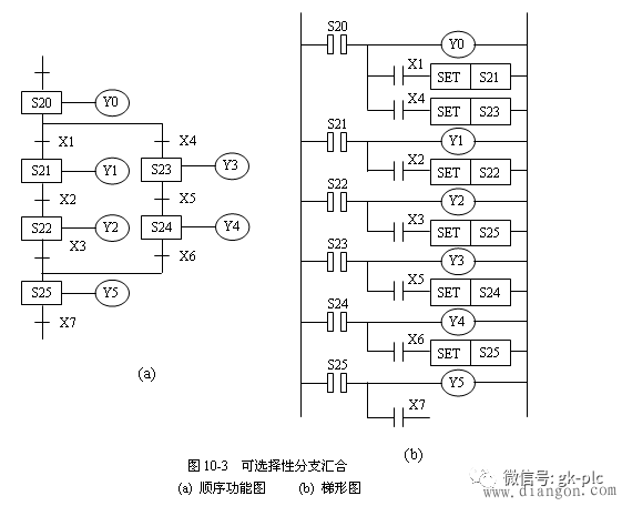
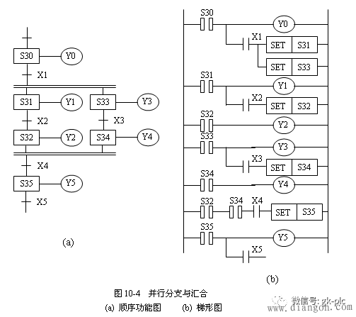
Step instruction programming is also one of the main methods for programming ladder programs based on sequential function diagrams. When designing a ladder diagram with a step command, first pay attention to the setting of the initial state relay. There are 1000 status relays (S0~S999) in Mitsubishi FX2N series plc, among which 10 are S0~S9 initial state relays, S10~S19 are return status relays, S20~S499 are general status relays, S500~S899 are Hold state relay, S900~S999 are alarm status relays. The number of times the status relay is used is not limited. It can also be used as an auxiliary relay when the status relay is not used for step sequence control. There are only two stepping instructions in the Mitsubishi FX2N series PLC: STL (step start command) and RET (step end command). The STL and RET instructions must be used in conjunction with the status relay S to have a step function. STL is also called a step contact command (1 step), and the STL ladder symbol is called, called STL contact, which has no break contact. Both STL S20 and STL S21 are STL contacts. In the ladder diagram, the STL contact is connected to the bus. After using the STL instruction, the bus moves to the right side of the contact, and then LD, LDI, OUT, etc. are used until the next STL instruction or the RET instruction appears. The STL instruction sets the new status relay, while the previous status relay is automatically reset and its contacts are open. Figure 10-1 shows the strict correspondence between sequential function diagrams, ladder diagrams, and statement tables. The step end instruction RET is also called a step return instruction, and the ladder symbol is used. The RET instruction must be used after a series of STL instructions to indicate the end of the step command function and the bus return to its home position. When writing a sequence control program using stepping instructions, first determine the flow of the entire control system, then decompose the complex task or process into several processes (states), and finally clarify the conditions for the establishment of each process, the conditions for the transfer of the process, and the transfer. The direction so that you can draw a sequence of function diagrams. According to the control requirements, the step sequence control using the STL and RET instructions can be performed in a variety of ways. Figure 10-2 shows the single-process sequence function diagram. In the figure, M8002 is a special auxiliary relay that is turned on instantaneously only at the beginning of the operation to generate an initial pulse. Figure 10-3 shows the selective branch and merge state transition mode. As shown in Figure 10-4, there is a parallel branch and merge state transition mode. 51V Battery Pack,Portable Battery Box,Portable Battery Bank,Ac Battery Pack Zhejiang Casnovo Materials Co., Ltd. , https://www.casnovo-new-energy.com