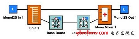
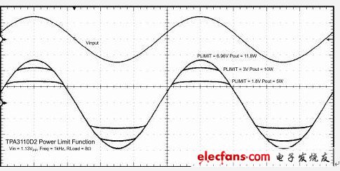
Many engineers who deal with speakers and amplifiers will tell you the same thing. If the amplifier is operated excessively, the driver of the speaker will be more or less damaged. This process usually involves gradually raising the bass knob, or sharply raising the volume knob. What will be the result of doing this? It may damage the tweeter driver of the speaker. But why does this result happen? Most tweeter drivers are designed for the 10W to 15W power range. Very little energy is required to drive them to work at high frequencies. The rated power of midrange and woofer is generally the average power of the entire speaker (50W and 100W, etc.). Think about what happens when you add gain to a sine wave (using a fixed power rail to play music) in a limiting system. At this point, the signal begins to clip. If you drive a signal beyond the limit, the waveform starts to look more like a square wave. From the perspective of the frequency domain, we begin to obtain the input signal harmonics. Due to the large amount of clipping, the harmonics appear to have higher amplitudes. Now, if you use a passive crossover, many high-order harmonics can easily go from the mid-bass driver crossover to the treble. Because the driver for high-frequency audio is extremely low, the probability of damage caused by it is also much higher. In many systems, this is a real problem, especially those that use simple analog processing (eg, operational amplifiers, op amps) or numerically controlled analog EQ systems. Two better solutions are: 1. Bi-amplifier system If in a closed system, such as: an active speaker, etc., please consider using a bi-amp for your system. The bi-amp allows you to use a separate amplifier to drive the treble. The separation between the treble and bass is completed before the low frequency gain, so that it can prevent the treble from damaging the high frequency part of the limited bass channel. The dual power amplifier system allows you to run most analog systems with highly flexible digital adjustment functions. The disadvantage is the high cost of increasing the amplifier. However, we must make a compromise between a good passive crossover and additional amplifier cost. Using a digital divider in a digital-to-analog converter (DAC) or a multimedia digital signal codec (Codec) can alleviate this problem to some extent. Fine-tuning your crossover digitally is much simpler than replacing various passive components. This also allows the same PCB design to be reused for speakers and speaker drivers of different sizes. Note that this system is only effective if you can directly access the two drives separately. 2. Intelligent post-processing limiter bass signal Some developers will use "soft clipping". This is a very simple method, but it is rare in home audio systems. Generally speaking, we will increase the low frequency bass frequency to the highest. Some developers will remove the bass boost of 24 dB in order to compensate for the low frequency response of small 2-inch drivers. If the frequency of the frequency increase is generally low, try adding a low-pass filter after the gain stage to reduce the high frequency caused by the limiting. In analog systems, using a sufficiently high cutoff rate to construct such a low-pass filter usually requires a multi-order filter, which makes the system bulky and costly. However, it can be easily implemented in digital processing systems, provided that there is sufficient effective MIPS in the audio processor. Figure 2 shows an example of a processing flow in soft clipping. Figure 1 High-gain DRC and low-pass filter processing flow From portable audio amplifiers such as TLV320AIC325x series devices to newer PCM514x home audio miniDSP DACs, these programmable miniDSP products can achieve soft limiting. Some smarter implementation methods rely on the majority of system developers to innovate. Each device integrates a fully programmable miniDSP core, so that developers are no longer bound by a fixed processing flow, and no need to copy other people's audio system design methods. Figure 2 Use PLimit to limit the output and ensure no high frequency harmonics For some people, this content may not be new. But for others, after reading this article, you may suddenly understand that "this is why my speaker is damaged!" Next time, we will discuss how to find the noise and spurious signals of high-speed DAC, so stay tuned.
Coupletech Co., Ltd manufactures, develops some kinds of Pockels Cell Q-switch driver and Pockels Cell Driver board, mini High Voltage Module for matching our pockels cell, Q-swithes. The voltage is up to 10KV, the repetition rate is up to 200kHz and the rising time/falling time is <10ns. The application is from Q-switching to more advanced pulse picking, pulse slicing and regenerative amplifier control.
Coupletech is seeking small volume, compact design, high laser power, high reliability for our electrooptics, and keeping satisfact quality as always. We supply Standard products, e.g. PCD20, PCD-C, and PCD-BS and customized products. Pockels Cell Driver Driver Board,High Voltage Power Supplies,Pockels Cell,Pockels Cell Modulator,Laser electronics,Q-switches,Pulse Picker Coupletech Co., Ltd. , https://www.coupletech.com