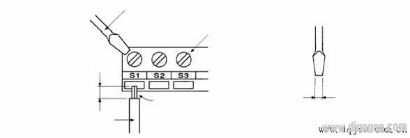
1. The signal line and the power line must be separated. When using the analog signal to remotely control the inverter, in order to reduce the interference of the analog quantity from the inverter and other equipment, please control the signal line and the strong circuit of the inverter (main The loop and the sequence loop are separated. The distance should be more than 30cm. Even in the control cabinet, it is necessary to maintain such wiring specifications. The control loop between this signal and the frequency converter must not exceed 50m. 2. The signal line and the power line must be placed inside different metal pipes or metal hoses respectively. Since the two Fuji inverters of the water system are 30m and 20m away from the control cabinet respectively, the signal lines connecting the plc and the inverter are It is not placed in the metal pipe and is easily interfered by the inverter and external equipment. At the same time, since the inverter has no built-in reactor, the input and output stage power lines of the inverter will have strong interference to the outside, so the signal line is placed. The metal tube or metal hose is always extended to the control terminals of the inverter to ensure complete separation of the signal line from the power line. 3. The analog control signal line should use double stranded shielded wire, and the wire size is 0.5~2mm2. When wiring, be sure to note that the cable stripping should be as short as possible (5-7mm), and the shield after stripping should be wrapped with insulating tape to prevent the shield from coming into contact with other equipment to introduce interference. 4. In order to improve the simplicity and reliability of the wiring, it is recommended to use the crimping bar terminal on the signal line. The crimp terminal is selected as shown below: 5. If there is no crimp terminal, please pay attention when wiring: 7. The grounding of the inverter should be grounded separately from the PLC control circuit. In the case that the grounding cannot be guaranteed separately, in order to reduce the interference of the inverter to the controller, the grounding of the control circuit can be floated, but the inverter must be reliably grounded. In the control system, it is recommended to float both ends of the shielded signal line of the analog signal line. At the same time, since the PLC and the inverter share a common ground on the unit, it is recommended to ground the PLC separately or connect the PLC to the unit when possible. Insulated. 8, the grounding of the inverter 9. Wiring distance between inverter and motor When the wiring distance between the inverter and the motor is long, the high-order harmonic leakage current from the cable will adversely affect the inverter and peripheral equipment. Therefore, in order to reduce the interference of the inverter, it is necessary to adjust the carrier frequency of the inverter, please refer to the following table:
24v wall charger,24v dc adapter,24v ac dc adapter,24v switching adapter,100-240V AC to DC 24V 3A 72W Power Adapter,12W Ac Switching Power Adapter,24V 0.5A Power Supply For Led Lights Shenzhen Waweis Technology Co., Ltd. , https://www.laptopsasdapter.com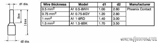
400V class: C type grounding (grounding resistance 10Ω or less).
Do not share the grounding wire with the welder and power equipment.
The grounding wire should be in accordance with the wire diameter specifications specified in the electrical equipment technical standards.
For example, the grounding wire diameter of the inverter of 35KW is recommended to be 22 mm2, and the grounding wire diameter of 87KW is recommended to be 50 mm2.
The ground wire is as short as possible. Since the inverter generates leakage current and the distance from the grounding point is too far, the potential of the grounding terminal is unstable.
When using two or more inverters, do not loop the ground wire. Figure: 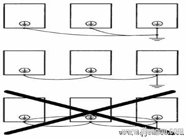
Wiring distance between inverter and motor is 50m or less, 100m or less, 100m or more, carrier frequency is 15KHz or less, 10KHz or less, 5KHz or less.
24V Switching Wall Charger

About this item