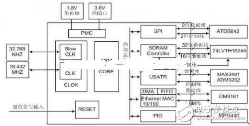
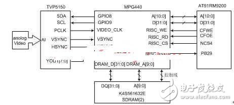
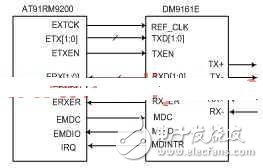
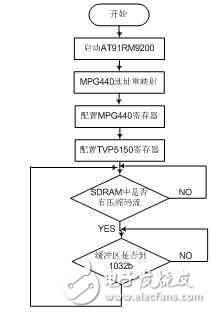
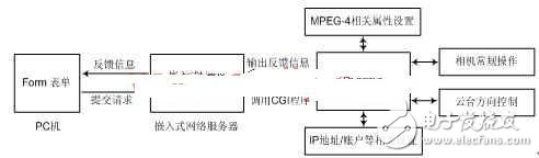
With the rapid development of communication technology and network technology, remote monitoring of important places through the network has attracted much attention. Network cameras have emerged in this context and have become the focus of attention. A network camera is a new generation of cameras that combines traditional camera and network technologies. It can transmit images to the other end of the globe through the network, and remote browsers do not need any professional software, as long as a standard web browser ( For example, “Microsoft IE or Netscape†can monitor its image. The network camera needs to transmit high-definition real-time video information to the monitoring terminal via the Internet. Because of its huge amount of information, it must be compressed. Usually people use DSP and MPEG-4 algorithm. The combination of solutions to achieve not only the large amount of programming work, but also the high cost of the product. The network camera introduced in this paper uses a dedicated MPEG-4 compression chip and embedded Linux as the operating system, which is not only easy to develop, but also low in cost. Good real-time performance and wide application range. The overall system design includes hardware design and software design. The two parts of the work are interrelated and need to be cross-over. The system design is the work carried out by the developers. They convert the logical model of the target system obtained in the system design stage into the physical model of the target system, and the work results are obtained in this stage. The design specification is the basis for the implementation of the system in the next phase. The hardware design module mainly includes a microcontroller module, and the microcontroller is a single-chip microcomputer that integrates a main part of the microcomputer on one chip. Microcontrollers were born in the mid-1970s. After more than 20 years of development, their cost is getting lower and lower, and their performance is getting stronger and stronger, which makes their applications ubiquitous in all fields. Examples include motor control, bar code readers/scanners, consumer electronics, gaming equipment, telephones, HVAC, building security and access control, industrial control and automation, and white goods (washing machines, microwave ovens). The compression coding module, the network interface module and the camera control module are four parts. The microcontroller module is mainly composed of a main control chip, DataFlash and SDRAM (1). Among them, the main control chip is the core of the entire control system, which is responsible for the scheduling of the entire system. DataFlash solidifies the embedded Linux kernel, its file system, application software, and system configuration files. The compression coding module is composed of a video data acquisition chip, an MPEG-4 compression coding chip, and an SDRAM (2), and is responsible for converting the video stream into an MPEG-4 code stream. The network interface module mainly cooperates with the main control chip to transmit the MPEG-4 code stream. The camera's control module is mainly composed of a serial port chip, which completes the function of forwarding and controlling camera commands. When the system starts, the microcontroller transfers the Linux kernel to SDRAM (1) via SPI (Serial Peripheral Interface), and the system boots from SDRAM (1). After the system is started, the microcontroller controls the MPEG-4 encoding module through the HPI (Host Peripherial Interface). The structure is shown in Figure 1. Figure 1 system block diagram The software design part mainly includes embedded Linux transplantation, MPEG-4 compression coding module, CGI control program and MPEG-4 decoding program. The embedded Linux system is stored in the DataFlash controlled by the AT91RM9200, which is responsible for the scheduling of the entire system software. The MPEG-4 compression coding module is mainly responsible for the acquisition of analog video streams and compresses the digital video stream into an MPEG-4 data stream. The CGI control program is primarily responsible for camera control and related settings for MPEG-4 video streams. CGI. Physically, it is a program that runs on the server and provides an interface to the client's HTML page. This is probably not easy to understand. So let's look at a practical example: Most of the current personal homepages have a guestbook. The work of the guestbook is like this: the user first enters some information on the client, such as a name. Then the user clicks on the "message" (so far works on the client), the browser transfers this information to the specific cgi program in the server's CGI directory, so the cgi program is processed on the server according to the predetermined method. In this case, the information submitted by the user is stored in the specified file. The cgi program then sends a message to the client indicating that the requested task has ended. At this point, the user will see the words "End of Message" in the browser. The whole process is over. The MPEG-4 decoding program is primarily responsible for the decoding of MPEG-4 data streams obtained over the network. The microcontroller is the core component of the system. It is ATMEL's AT91RM9200. It is a 32-bit microcontroller based on the ARM920T core. Its main frequency is 180MHz, the processing speed is fast, the function is strong, the cost performance is high, and it can meet the requirements of embedded Linux system well. Its main function in the system is to configure the function registers of other chips when the system is powered on, to schedule and control the whole system work under normal working conditions, and to control the physical layer chip to send the code stream through the on-chip Ethernet controller. AT91RM9200 realizes the control of peripheral DataFlash and SDRAM through the on-chip SPI bus and SDRAM controller. It controls the serial port chip by using the on-chip USART, and controls the off-chip network chip through the on-chip Ethernet controller. The control schematic diagram is shown in Figure 2. Figure 2 control schematic The compression coding module includes an analog video acquisition module and an MPEG-4 compression module. The video acquisition chip adopts TVP5150 of TI Company, and the data compression chip adopts MPG440.TVP5150 input end of Yingjia Company. It can be two kinds of mixed video signals or video signals of S-Video terminal, and supports three kinds of standards such as NTSC, PAL and SECAM. The output data color format can be an 8-bit 4:2:2 digital signal or an 8-bit synchronous ITU-R BT.656 digital signal. The MPG440 chip has an industry-standard 16b/32b bidirectional host interface for communication with video capture chips and microcontroller chips. At the same time, it has features such as motion detection, anti-counterfeiting watermark, dynamic adjustment of IP frame ratio, and dynamic adjustment of image quality. It supports five resolution modes: D1, VGA, CIF, QVGA, and QCI. The hardware design principle of the micro compression coding module is shown in Figure 3. Figure 3 compression coding circuit The AI ​​analog input of the TVP5150 is connected to the analog camera output to transmit analog video signals to the video processing chip. After the analog signal is sampled, it is sent to MPG440 through the YOUT0~YOUT7 pin. The sampled data is valid on the rising edge of PCLK. The VIDEO_CLK of MPG440 receives the signal of YOUT when it receives the rising edge of PCLK. The TVP5150 sub-field sync pulse and the line sync pulse correspond to the output terminals VSYNC and HSYNC.MPG440, respectively. The field sync and line sync operations of the image are realized according to the VSYNC and HSYNC signal lines connected thereto. The video input data lines DATA_TV0~DATA_TV7 of the MPG440 are connected to YOUT0~YOUT7 of the TVP5150. While receiving the data, the MPG 440 transmits the obtained data stream to the MPEG-4 compression coding unit, and the encoded MPEG-4 data stream is temporarily stored in the SDRAM (2). The MPG440 on-chip PDMA controller accurately initiates access to the SDRAM (2) according to the configuration register settings, and simultaneously delivers the resulting data stream to the HPI (Host Peripherial Interface) to wait for the AT91RM9200 to send data to the network through the DMA channel. . MPG440 communicates with AT91RM9200 through HPI. AT91RM9200 uses MPG440's registers, storage space and other resources as its own memory address access. The MPG440 is gated by the AT91RM9200 strobe line NCS4. The address segment in the AT91RM9200 addressing space is 0X50000000 to 0X5FFFFFFF. By setting the MPG440 series of registers, the MPG440 system memory space can be accessed. The MPG440 interrupt signal RSC_INT0 is input from the PB29 of the general-purpose I/O pin. When the buffer is full, the RSC_INT0 pin is deasserted to prompt the AT91RM9200 to extract the MPEG-4 data stream through the DMA channel. The encoded video data reading process and the MPG 440 and host communication process are controlled by the AT91RM9200 read signal CFRD and the write signal CFWE. The network module hardware design principle is shown in Figure 4. Figure 4 network module circuit The AT91RM9200's on-chip Ethernet card port communicates with the MII interface of the network physical layer chip DM9161E. When transmitting data, first set the transmit enable signal ETXEN to be valid. The data transmitting end ETX0~ETX1 is connected to the ETXO~ETX1 pins of the DM9161, and is used as a data transmission channel to transmit data with the DM9161E clock signal REF_CLK. The data receiving end ERX 0~ERX1 is connected to the RXDO~RXD1 pin of the DM9161E as a data receiving channel. The management clock signal EMDC and the management data input and output signal EMDIO are used for writing and reading of chip control parameters. The MDINTR terminal of the DM9161E is used to generate an interrupt signal. The on-chip Ethernet card transmits data through the DMA channel without affecting the normal operation of the AT91RM9200. Firstly, the parameters of the transfer data block number and the data block storage first address of the transfer control register and the transfer address register are correctly set, and then 1024b data is sequentially read from the specified data storage area address and sent to the internal transmission buffer by the MAC pair. The data is encapsulated and sent, and the number of bytes transferred is recorded until the data block is sent. After sending a set of data, a DMA interrupt request is issued, and the AT91RM9200 performs corresponding processing. The entire network subsystem circuit is controlled and scheduled by the AT91RM9200. The embedded Linux system mainly consists of four parts: a bootloader that boots the kernel, a Linux kernel (kernel), a virtual disk file (ramdisk), and a user space file (user). They are placed in four partition modules within the DataFlash. According to the specific functions of different modules, different file systems are used: bootloader, kernel, ramdisk, no dynamic changes are needed after the migration is completed, and a more space-saving ROMFS read-only file system is used; some configuration files that can be dynamically updated are placed in the user module. More read and write operations are required, so use the JFFS2 file system that supports dynamic erase and write. Inux is the advantage of embedded. First, Linux is open source. There is no black box technology. Many Linux enthusiasts around the world are powerful technical support for Linux developers. Secondly, Linux has small kernel, high efficiency, and kernel. The update speed is very fast, linux can be customized, the system kernel is only about 134KB minimum. Third, Linux is a free OS, which is very competitive in price. Linux also has many features required for embedded operating systems. The outstanding thing is that Linux is suitable for multiple CPUs and multiple hardware platforms. It is a cross-platform system. So far, it can support twenty or thirty CPUs. It has stable performance, good cutting performance, and is easy to develop and use. Linux porting technology has matured and will not be elaborated in this article. The following mainly introduces the programming of the MPEG-4 compression coding module and the CGI module. This module mainly completes the configuration of MPG440 and TI5150 related registers, and guarantees the normal output of MPEG-4 code stream. After the embedded Linux system is started, the related registers of the MPG440 are first configured. After the initialization is completed, the TVP5150 is initialized and configured through the I2C bus. When the system starts compression encoding, the MPEG-4 stream reception storage program is controlled by the MPEG-440 data stream buffer flag signal. The program flow of MPEG-4 compression coding module is shown in Figure 4. Figure 5 MPEG-4 compression coding module program flow chart CGI (Common Gateway Interface) is a standard interface for external extension applications to interact with WWW servers. The working process of the system CGI: input the IP address of the network camera in the IE browser on the PC side, and the embedded web server feeds back the corresponding control page to the IE browser according to the request, the user fills in the form, and then submits, the CGI program extracts the form. The information is processed according to different information, such as adjusting MPEG-4 related attributes, camera related operations, and the like. The CGI control principle is shown in Figure 5. Figure 6 CGI control schematic
Our Surface Mount Box could include the CAT5E CAT6 CAT6A RJ45 Connectors
The surface mount box is an ideal for wall box and wire installation, we design many junction box, back mount box, blank mount box, loaded surface mount box.
Mateiral: ABS, PBT UL94V-0
1~8 ports and colors supply for your choice, they are an ideal for low voltage application for your security, data, networking solutions and telecom projects.
CAT5E Surface Mount Box,Surface Mount Box,Adapter Inline Coupler,single port junction surface mount box NINGBO UONICORE ELECTRONICS CO., LTD , https://www.uniconmelectronics.com
Shallow embedded network camera design
1 Introduction