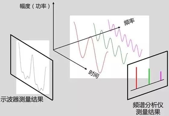
A spectrum analyzer is an instrument that studies the spectrum structure of electrical signals. It is used to measure signal parameters such as signal distortion, modulation, spectral purity, frequency stability, and intermodulation distortion. It can be used to measure certain circuit systems such as amplifiers and filters. Parameter is a multi-purpose electronic measuring instrument. It can also be called frequency domain oscilloscope, tracking oscilloscope, analysis oscilloscope, harmonic analyzer, frequency characteristic analyzer or Fourier analyzer, etc. Modern spectrum analyzers can display the analysis results in an analog or digital manner, and can analyze electrical signals in all radio frequency bands from very low frequencies below 1 Hz to sub-millimeter wave bands. If the digital circuit and microprocessor are used inside the instrument, it has storage and calculation functions; with a standard interface, it is easy to form an automatic test system. The spectrum analyzer is a commonly used analysis instrument, mainly for the detection of radio frequency and microwave signals, and has certain applications in many fields. Question and answer area There are some common problems in the use of spectrum analyzers that need users' attention. Today I will introduce you to the six common problems in the use of spectrum analyzers. I hope they can help you. Q1: How to set up to obtain the best sensitivity of the spectrum analyzer, so as to facilitate the observation of small signals? A: First set the corresponding center frequency, span and reference level according to the size of the small signal being measured; then gradually reduce the attenuation value without the overload prompt of the spectrum analyzer. If the signal-to-noise ratio of the small signal under test is less than 15db, gradually reduce rbw. The smaller the rbw, the lower the noise floor of the spectrum analyzer and the higher the sensitivity. If the spectrum analyzer has pre-play, turn on the pre-play. Pre-opening can increase the noise figure of the spectrum analyzer, thereby improving the sensitivity. For small signals with low signal-to-noise ratio, you can reduce vbw or use trajectory averaging to smooth noise and reduce fluctuations. It should be noted that the measurement result of the spectrum analyzer is the sum of the external input signal and the internal noise of the spectrum analyzer. To make the measurement result accurate, the signal-to-noise ratio is usually required to be greater than 20db. Q2: Is the resolution bandwidth (rbw) as small as possible? A: The smaller the rbw, the better the sensitivity of the spectrum analyzer. However, the scanning speed will become slower. Well set up rbw according to the actual test requirements to find a balance between sensitivity and speed-not only to ensure accurate measurement of the signal but also to get a fast measurement speed. Q3: How to choose the average detection method (averagetype): power? logpower? voltage? Logpower logarithmic power average: also known as videoaveraging, this averaging method has a low noise floor and is suitable for low-level continuous wave signal testing. But there will be certain errors for "noise-like" signals, such as wideband modulated signals w-cdma, etc. Power averaging: also known as rms averaging, this averaging method is suitable for total power measurement of "noise-like" signals (eg cdma). Voltage averaging: This averaging method is suitable for observing the rise and fall times of amplitude modulation signals or pulse modulation signals. Q4: Selection of scanning mode: sweep or fft? A: The scan mode of modern spectrum analyzers usually has sweep mode and fft mode. Usually in the narrow rbw setting, fft has a speed advantage over sweep, but in the wider rbw condition, the sweep mode is faster. When the span is less than the analysis bandwidth of fft, the fft mode can measure transient signals; when the span exceeds the fft analysis bandwidth of the spectrum analyzer, if the fft scan mode is used, the working method is to process the signal in sections There is a discontinuity in time between the time, then the useful signal may be lost during the signal sampling gap, and there will be distortion in the spectrum analysis. This type of signal includes: pulse signal, tdma signal, fsk modulation signal, etc. Q5: How does the choice of detector affect the measurement result? Peak detection method: select the large value in each bucket as the measured value. This detection method is suitable for continuous wave signal and signal search test. Sample detection method: This detection method is usually suitable for testing noise and "noise-like" signals. negpeak detection method: suitable for small signal test, for example, emc test. Normal detection mode: suitable for observing signal and noise at the same time. Q6: What is the role of tracking source (tg)? A: The tracking source is one of the common options on the spectrum analyzer. When the output of the tracking source passes through the input port of the device under test and the output of this device is connected to the input port of the spectrum analyzer, the spectrum analyzer and the tracking source form a complete adaptive swept frequency measurement system. Tracking the frequency of the signal output by the source can accurately track the tuning frequency of the spectrum analyzer. The spectrometer with optional tracking source can be used as a simple scalar network analysis to observe the excitation response characteristic curve of the device under test, such as the frequency response and insertion loss of the device. REMOTE CONTROL SOCKET
Programming Instructions
•Press any ON switch on the Remote Control for approximately 2 seconds and the Remote Socket(s) learn the code. The LED will stop flashing top confirm the codehas been accepted. remote switch,remote plug,remote control switch,remote power switch,remote control sockets NINGBO COWELL ELECTRONICS & TECHNOLOGY CO., LTD , https://www.cowellsocket.com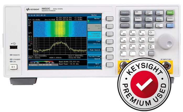
Important Safeguards
When using any electrical appliance, in order to reduce the risk of fire, electric shock and/or injury to persons, basic safety precautions should always be follow8d. including:
• The appliance is for household and indoor use only.
• Before plugging in. check that the voitage on the rating label is the same as the mains supply.
• To protect against electric shock, do not immerse any part of the product in water or other liquid.
• This socket is intended for use by competent adults only and children should be supervised at all times.
• Do not use the socket for other than its intended use.
• This socket can be used by children aged from 8 years arxl above and persons with reduced physical, sensory or mental capabilities or lack of experience and knowledge if they have been given supervision or instruction concerning use of the appliance in a safe way and understand the hazards involved. Children shall not p<ay with the appliance Cleaning and user maintenance shall M be made by children without supervision.
• Children of less than 3 years should be kept away unless continuously supervised.
Children from 3 years and less than 8 years shall only switch on/off the appliance provided that it has been placed or installed in its intended normal operating position and they have been supervision or instruction concerning use of the appliance in a safe way and understand the hazards involved. Children aged from 3 years and less than 8 years shall not plug in. regulate and clean the appliance or perform user maintenance.
• Don't use this socket in the immediate surroundings of a bath, a shower or a swimming pool.
• In case of malfunction, do not try to repair the socket yourself, it may result in a fire hazard or electric shock
Do Not Exceed Maximum a680W
Place the LR44 batteries provided into the compartment in the back of the Remote Control, please insert as sho*/m in the back of the compartment to ensure the polarity is correct.
• Plug the Remoce Socket$($)lnto the wall socket(s) and switch on the mams supply, the red LED will flash every second.
• If the LED is not flashing press & hold the manual ON/OFF button for 5 seconds until it Hashes
• Any number of Remote Sockets can be programmed to one Remote Control ON button to create multiple switching.
• To programme o<her Remote Sockets on different Remote Control ON buttons repeat the prevous steps
• If the mains supply is turned off the Remote Sockets v/ill lose their code and it wil be necessary to re-pcogramme.
Operation:
• Plug your appliance(s) into the Remote Socket(s)
• Press the programmed ON or OFF button on the Remote Control to control the Remote Socket.
♦ The Remote Sockets can also be operated manually using its ON/OFF Button Trouble shooting
If a Remote Socket does not react to the Remote Control please check the followng:
♦ Low battery in tbo Remote Control
• Distance too large between the remote control and the recerver (ensure the range distance is no more than 20 clear Metres) and free from obstacle that may reduce the distance.
• If programming has not been successful, tum the power off and back on then follow the programming steps above.
How to decode
• Press the manual ONX)FF button for 5 seconds until the red LED flashes once per
second to confirm de-coding is successful
♦ Press the ALL OFF switch on the Remote Control for more than 3 seconds, the LED
flashes once per second to confirm (decoding successful.
Voltage: 240V-/50HZ
Max power rating: 3680W max.
Remote frequency:
Remote range:
Battery Type:
433.92MHz
230 Metres
Button Cell 2x1.5V LR44 =
Please check with your local waste management service authority regarding regulations for the safe disposal of the batteries. The batteries should never be placed G municipal waste.
Use a battery d^posal facility if available
M
For eioctncal products sold within the European Community. At the end of the electrical products useful life, it should not be disposed of wth household waste. Please recycle faaMies exist. Check with your Local Authonty or retailer for recycling advice.
C€