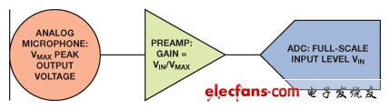
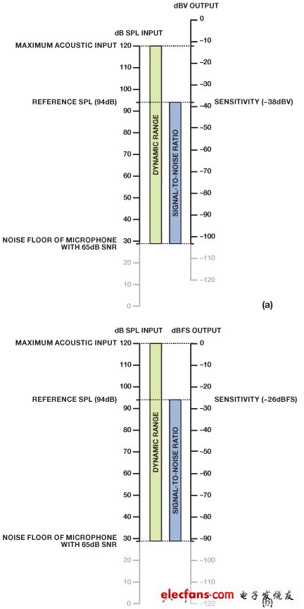
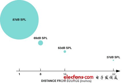
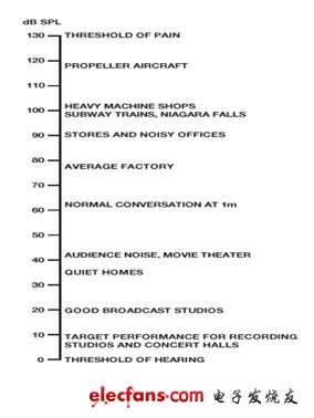
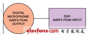
Sensitivity, which is the ratio of analog output voltage or digital output value to input pressure, is a key indicator for any microphone. When the input is known, the mapping from the acoustic domain unit to the electrical domain unit determines the amplitude of the microphone output signal. This article will discuss the differences in sensitivity specifications between analog and digital microphones, how to choose the microphone with the best sensitivity according to the specific application, and also discuss why adding one (or more) digital gain can enhance the microphone signal. Analog and digital The microphone sensitivity is generally measured at a sound pressure level (SPL) of 94 dB (or pressure of 1 Pa) with a 1 kHz sine wave. The analog or digital output signal amplitude of the microphone under this input excitation is a measure of microphone sensitivity. This reference point is only one of the characteristics of the microphone, and does not represent the entire performance of the microphone. The sensitivity of an analog microphone is simple and not difficult to understand. This index is generally expressed in logarithmic units of dBV (decibels relative to 1 V), which represents the volts of the output signal at a given SPL. For analog microphones, the sensitivity (expressed in linear units mV / Pa) can be expressed in decibels in logarithm: Where OutputAREF is 1000 mV / Pa (1 V / Pa) reference output ratio. With this information and the correct preamp gain, it is easy to match the microphone signal level to the target input level of the circuit or Other Parts of the system. Figure 1 shows how to set the microphone's peak output voltage (VMAX) to match the ADC's full-scale input voltage (VIN) with a gain of VIN / VMAX. For example, with a gain of 4 (12 dB), an ADMP504 with a maximum output voltage of 0. 25 V can be matched to an ADC with a full-scale peak input voltage of 1.0 V. Figure 1. Analog microphone input signal chain with preamplifier to match microphone output level to ADC input level The sensitivity of a digital microphone (in dBFS, decibels relative to digital full scale) is not so simple. The difference in units indicates that there is a subtle difference in the definition of the sensitivity of digital microphones and analog microphones. For analog microphones that provide voltage output, the only limitation on the size of the output signal is actually the limitation of the system power supply voltage. Although not practical for most designs, physically speaking, analog microphones can have a sensitivity of 20 dBV, and the output signal used for the reference level input signal is 10 V. As long as the amplifier, converter and other circuits can support the required signal level, this level of sensitivity can be achieved. The sensitivity of the digital microphone is not so flexible, but only depends on one design parameter, namely, the maximum acoustic input. As long as the full-scale digital word is mapped to the microphone's maximum acoustic input (in fact, this is the only useful mapping), the sensitivity must be the difference between this maximum acoustic signal and the 94 dB SPL reference signal. Therefore, if the maximum SPL of a digital microphone is 120 dB, its sensitivity is –26 dBFS (94 dB – 120 dB). Unless the maximum acoustic input is reduced by the same amount, it is impossible to adjust the design to make the digital output signal of a given acoustic input higher. For digital microphones, the sensitivity is expressed as the percentage of the full-scale output produced by the 94 dB SPL input. The conversion formula of the digital microphone is Where OutputDREF is the full-scale digital output level. Now let's compare the last very difficult point, digital and analog microphones are not consistent in the use of peak level and rms level. The microphone's acoustic input level (in dB SPL) is always a rms measurement, regardless of the type of microphone. The output of the analog microphone is referenced to 1 V rms, because the root-mean-square measurement is more commonly used to compare analog audio signal levels. However, the sensitivity and output level of digital microphones are expressed as peak levels because they are referenced to full-scale digital words (ie peaks). In general, when configuring downstream signal processing that may rely on accurate signal levels, you must remember the convention of specifying the output of a digital microphone with peak levels. For example, dynamic range processors (compressors, limiters, and noise gates) usually set thresholds based on the rms signal level, so the output of the digital microphone must be scaled by reducing the dBFS value from peak to rms . For a sinusoidal input, the rms level is 3 dB lower than the peak level (that is, the logarithmic measurement of (FS√2)); for more complex signals, the The difference may be different. For example, the ADMP421, a MEMS microphone that provides a pulsed density modulation (PDM) digital output has a sensitivity of –26. A 94 dB SPL sinusoidal input signal will produce a peak output level of –26 dBFS, or an rms level of –29 dBFS. Because the output of digital microphones and analog microphones use different units, it may be difficult to understand when comparing the two types of microphones; but the two have a common unit of measurement in the sound domain, SPL. One microphone may be an analog voltage output, the other is a modulated PDM output, and the other is an I2S output, but their maximum acoustic input and signal-to-noise ratio (SNR, the difference between the 94 dB SPL reference level and the noise level ) Is directly comparable. Using the sound range rather than the output format as a reference, these two specifications provide a convenient way to compare different microphones. Figure 2 shows the relationship between the acoustic input signal and output level of analog and digital microphones at a given sensitivity. Figure 2 (a) shows the ADMP504 analog microphone with a sensitivity of –38 dBV and a signal-to-noise ratio of 65 dB. Changing the sensitivity relative to the 94 dB SPL reference point on the left will result in the following: sliding the dBV output bar upward will decrease the sensitivity, and sliding the output bar downward will increase the sensitivity. Figure 2. (a) Mapping the acoustic input level to the voltage output level (analog microphone) (B) Mapping the acoustic input level to the digital output level (digital microphone) Figure 2 (b) shows the ADMP521 digital digital microphone with a sensitivity of -26 dBFS and a signal-to-noise ratio of 65 dB. The schematic diagram of the input-to-output level mapping of the digital microphone indicates that adjusting the sensitivity of the microphone will destroy the mapping between the maximum acoustic input and the full-scale digital word. Compared with sensitivity, SNR, dynamic range, power supply rejection ratio, THD and other specifications can better show the performance of the microphone. Select sensitivity and set gain High sensitivity microphones are not always better than low sensitivity microphones. Although sensitivity can show some characteristics of the microphone, it may not necessarily reflect the performance of the microphone. The balance between microphone noise level, clipping point, distortion and sensitivity determines whether the microphone is suitable for a specific application. A high-sensitivity microphone may require less preamp gain before analog-to-digital conversion, but its margin before clipping may be less than a low-sensitivity microphone. In near-field applications such as mobile phones, where the microphone is close to the sound source, microphones with higher sensitivity are more likely to reach the maximum acoustic input, causing clipping, and eventually distortion. On the other hand, higher sensitivity may be suitable for far-field applications (such as conference phones and security cameras), because in such applications, as the distance between the microphone and the sound source increases, the sound will be attenuated. Figure 3 shows how the distance between the microphone and the sound source affects the SPL. Each time the distance from the sound source doubles, the acoustic signal level will drop by 6 dB (half). Figure 3. As the distance from the sound source increases, the microphone sound pressure level will decrease For reference, Figure 4 shows the typical SPL of various sound sources, from a quiet recording studio (below 10 dB SPL) to a pain threshold (below 130 dB SPL). The pain threshold refers to the point where sound brings pain to normal people. Microphones rarely cover the entire range—or even roughly—the range, so choosing the right microphone for the required SPL range is an important design decision. Sensitivity specifications should be used to match the output signal level of the microphone in the entire target dynamic range to the common signal level of the audio signal chain. Figure 4. Sound pressure levels of various sound sources The sensitivity range of the analog microphone is wide. The sensitivity of some dynamic microphones may be as low as –70 dBV. Some condenser microphone modules have integrated pre-amplifiers and therefore have extremely high sensitivity, reaching –18 dBV. The sensitivity of most analog electret microphones and MEMS microphones is between –46 dBV to –35 dBV (5.0 mV / Pa to 17.8 mV / Pa). This level represents a good compromise between the noise floor (ADMP504 and ADMP521 MEMS microphones may be as low as 29 dB SPL) and the maximum acoustic input (typically about 120 dB SPL). The sensitivity of the analog microphone can be adjusted in a preamp circuit, which is usually integrated in the package with the sensor element. Although the sensitivity of the digital microphone seems to lack flexibility, the level of the microphone signal can be easily adjusted by the gain in the digital processor. For digital gain, as long as the number of bits in the processor is sufficient to fully represent the dynamic range of the original microphone signal, it will not cause a reduction in the noise level of the signal. In analog design, each gain stage introduces some noise into the signal; the system designer is required to ensure that the noise of each gain stage is low enough to avoid injecting noise and reducing the audio signal. For example, we can look at the ADMP441, which is a digital (I2S) output microphone with a maximum SPL of 120 dB (sensitivity of –26 dBFS) and an equivalent input noise of 33 dB SPL (61 dB SNR). The dynamic range of this microphone is the difference between the maximum signal (maximum SPL) and the minimum signal (noise floor) that can be reliably reproduced (ADMP441: 120 dB – 33 dB = 87 dB). This dynamic range can be reproduced with a 15-bit data word. When the data in the digital word is shifted by 1 bit, the signal level will shift by 6 dB. Therefore, even a 16-bit audio processor with a dynamic range of 98 dB can use 11 dB of gain or attenuation without affecting the original dynamic range. Note that in many processors, the maximum acoustic input of the digital microphone is mapped to the DSP's internal full-scale level. In this case, increasing any gain will cause the dynamic range to decrease by the same amount, thereby reducing the system's clipping point. Taking the ADMP441 as an example, in a processor with no margin above full scale, increasing the gain by 4 dB will cause the system to clip the 116 dB SPL signal. Figure 5 shows a digital microphone that provides I2S or PDM output and is directly connected to a DSP. In this signal chain, there is no need to use an intermediate gain stage because the microphone's peak output level already matches the DSP's full-scale input word. Figure 5. Digital microphone input signal chain directly connected to a DSP Conclusion This article explains how to understand the sensitivity specifications of the microphone and how to apply it to the gain stage of the system. It also explains why the sensitivity is related to SNR, but it does not reflect the quality of the microphone like SNR. Whether designing with an analog microphone or a digital MEMS microphone, this article will help designers choose the microphone that is most suitable for a specific application, so as to maximize the potential of the microphone. Our company is specialized in supplying Copper Tube which is most often used for supply of hot and cold tap water, and as refrigerant line in HVAC systems. Our copper tube has a feature of clean surface,bright finish,even structure,high precision size,welding easily, good shaping.The executive standard of the pancake coil is GB/T17791-2007,ASTMB280,JIS H3300.The executive standard of Straight Copper Pipe is GB/T 17791-2007,ASTM B280,JIS H3300,ASTMB88.We also could supply inner-grooved tube and insulated copper tube. Our parts have been exported to over 50 countries all over the world. Copper Tube Air Conditioner Copper Pipe,Refrigeration Copper Pipe,Refrigerant Copper Pipe,Straight Copper Pipe ZHEJIANG ICE LOONG ENVIRONMENTAL SCI-TECH CO.,LTD. , https://www.ice-loong.com