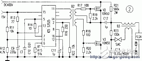
Solar cells are used in road lighting and are currently rapidly developing. When used in conjunction with batteries to ignite 35W to 70W low-power high-pressure sodium lamps and metal halide bulbs, the ballasts used must have low power consumption and high efficiency in order to achieve optimal electro-optic performance. Conversion efficiency. The electronic ballast described in this article has a quiescent current of 150mA and an efficiency of 95%, which is a self-trigger circuit. The circuit is now analyzed as follows. 2. Power amplification is shown in Fig. 2. The oscillating drive adopts S3525 integrated block. The signals output by the (11) pin and (14) pin are coupled via the transformer B2, and the secondary output is driven by two sets of voltage to drive the two MOS transistors V2 and V3. The lamp is lighted secondary by capacitor C12 and transformer B3. The operating frequency of S3525 is set at about 20 kHz, and it is obtained by adjusting the values ​​of the 5-pin C10 and the 6-pin R15. The turns ratio of transformer B2 is 100:50:50. When winding B2, pay attention to the same side of the secondary windings to prevent the power transistors V2 and V3 from turning on. 3. Trigger Circuit In Figure 2, DC400V voltage charges C13 through resistors R21 and R23. When charged to the bidirectional trigger diode SIAC turning voltage 150V, it turns on. The transformer secondary has nearly 3kV pulse voltage to trigger the ignition lamp. The winding ratio of the two windings of the transformer B3 is 1:20. By changing the values ​​of R2l and C13, the level of the trigger voltage can be adjusted to adapt to different types of light bulbs. This product is easy to use, in the non-220V power supply areas, such as the resident islands, deep mountains, park tourism destinations, all need street lights, if with solar cells, batteries, practical value is higher.
Whaylan On/Off Grid Solar Inverter
Pure sine wave output
On/Off Grid Solar Inverter,Hybrid Inverter With Mppt Charge,pure sine wave solar inverter suzhou whaylan new energy technology co., ltd , https://www.whaylan.com
1. Inverter circuit shown in Figure 1, the battery DC24V voltage after C1 filter ICl regulator, get 15V voltage, for the post-level IC2 and Vl work, where IC2 is the core of the boost circuit, the working principle has been described in many articles, No longer elaborated, IC2's 6-pin output signal drives the power transistor V1 to work, V1 can be used in parallel with multiple tubes. Switching transformer B1 secondary output voltage, after VDl rectification, C7 filtering and high-precision regulator block IC4, get a stable 400V voltage, change R10 resistance can be adjusted output voltage. 

The electrical waveform output of PH1800 is pure sine wave, which has the same quality as practical power supply or household power supply. This waveform is suitable for most electrical equipment, appliances and tools. This pure sine wave unit provides more functions than an improved sine wave inverter because it has a cleaner form of power. Pure sine wave can also reduce the noise generated when applying electrical appliances to a limited extent.
