The circuit of the inverter is generally composed of four parts: rectification, intermediate DC link, inverter and control. The rectification part is a three-phase bridge type uncontrollable rectifier, the inverter part is an IGBT three-phase bridge inverter, and the output is a PWM waveform, and the intermediate DC link is filtering, DC energy storage and buffer reactive power. The frequency converter is a power control device that converts the power frequency power source into another frequency by using the on/off function of the power semiconductor device. The inverter we use now mainly adopts AC-DC-AC (VVVF frequency conversion or vector control frequency conversion). First, the power frequency AC power supply is converted into DC power through the rectifier, and then the DC power is converted into frequency and voltage. AC power is supplied to the motor. The circuit of the inverter is generally composed of four parts: rectification, intermediate DC link, inverter and control. The rectification part is a three-phase bridge type uncontrollable rectifier, the inverter part is an IGBT three-phase bridge inverter, and the output is a PWM waveform, and the intermediate DC link is filtering, DC energy storage and buffer reactive power. Inverter control schematic design analysis: 1) First confirm the installation environment of the inverter; I. Working temperature. The inside of the inverter is a high-power electronic component, which is highly susceptible to the operating temperature. The product is generally required to be 0 to 55 ° C. However, in order to ensure safe and reliable operation, consideration should be given to leaving room for use. It is best to control below 40 ° C. . In the control box, the inverter should generally be installed in the upper part of the cabinet, and strictly follow the installation requirements in the product manual. It is absolutely not allowed to install the heating element or the heat-prone component close to the bottom of the inverter. II. Ambient temperature. When the temperature is too high and the temperature changes greatly, the inside of the inverter is prone to condensation, and its insulation performance is greatly reduced, and may even cause a short circuit accident. If necessary, desiccant and heater must be added to the tank. In the water treatment room, the water vapor is generally heavy. If the temperature changes greatly, this problem will be more prominent. III. Corrosive gases. If the concentration of corrosive gas is large, it will not only corrode the leads of the components, printed circuit boards, etc., but also accelerate the aging of the plastic devices and reduce the insulation performance. IV. Vibration and shock. When the control cabinet equipped with the inverter is subjected to mechanical vibration and shock, it may cause poor electrical contact. Huai'an Thermal Power has such problems. At this time, in addition to improving the mechanical strength of the control cabinet, away from the vibration source and the impact source, the anti-vibration rubber pad should also be used to fix the vibration-generating components such as the control cabinet and the internal electromagnetic switch. After the equipment has been in operation for a period of time, it should be inspected and maintained. V. Electromagnetic interference. Due to the rectification and frequency conversion, the inverter generates a lot of interference electromagnetic waves around the inverter. These high-frequency electromagnetic waves have certain interference to nearby instruments and instruments. Therefore, the instrument and electronic system in the cabinet should use a metal casing to shield the inverter from interference with the instrument. All components should be grounded reliably. In addition, shielded control cables should be used for wiring between electrical components, instruments and meters, and the shielding layer should be grounded. If the electromagnetic interference is not handled well, the whole system will not work, resulting in failure or damage of the control unit. 2) The distance between the inverter and the motor determines the cable and wiring method; I. The distance between the inverter and the motor should be as short as possible. This reduces the capacitance of the cable to ground and reduces the source of interference. II. The control cable is shielded cable. The power cable is shielded or shielded from the inverter to the motor. III. The motor cable should be independent of other cable traces with a minimum distance of 500mm. At the same time, the motor cable should be avoided to run parallel with other cables in a long distance, so as to reduce the electromagnetic interference caused by the rapid change of the output voltage of the inverter. If the control cable and the power cable cross, they should be crossed as much as possible at a 90 degree angle. The analog signal lines associated with the drive are routed separately from the main return line, even in the control cabinet. IV. It is best to use shielded twisted pair for the analog signal line related to the inverter. The power cable should be shielded with three-core cable (the specification is larger than that of the ordinary motor) or follow the inverter's user manual. 3) Inverter control schematic diagram; I. Main circuit: The function of the reactor is to prevent the higher harmonics generated by the inverter from returning to the grid through the input loop of the power supply and affecting other power receiving equipment. It is necessary to determine whether the reactor needs to be added according to the capacity of the inverter; The filter is installed at the output of the inverter to reduce the higher harmonics of the inverter output. When the distance from the inverter to the motor is far away, the filter should be installed. Although the inverter itself has various protection functions, the phase loss protection is not perfect. The circuit breaker is overloaded in the main circuit and lacks equal protection. When selecting the type, it can be selected according to the capacity of the inverter. The Thermal Relay can be replaced by the overload protection of the inverter itself. II. Control loop: manual switching with power frequency frequency conversion, in order to manually cut the power frequency operation when the frequency conversion fails, because the output terminal can not add voltage, the solid power frequency and the frequency conversion must have interlocking. 4) Grounding of the inverter; Proper grounding of the inverter is an important means to improve system stability and suppress noise. The grounding resistance of the grounding terminal of the inverter is as small as possible. The cross section of the grounding conductor is not less than 4mm and the length is not more than 5m. The grounding of the inverter should be separated from the grounding point of the power equipment and cannot be grounded. One end of the shield of the signal line is connected to the ground of the inverter, and the other end is floating. The inverter is electrically connected to the control cabinet. Common fault analysis: 1) Overcurrent fault: Overcurrent fault can be divided into acceleration, deceleration, and constant speed overcurrent. It may be caused by the acceleration/deceleration time of the inverter being too short, the load is abrupt, the load is not evenly distributed, and the output is short-circuited. At this time, it is generally possible to extend the acceleration/deceleration time, reduce the sudden change of the load, apply the energy-consuming braking element, carry out the load distribution design, and inspect the line. If the load inverter is disconnected or the overcurrent fault occurs, the inverter inverter circuit has been looped and the inverter needs to be replaced. 2) Overload fault: Overload fault includes inverter overload and motor overload. It may be caused by the acceleration time being too short, the grid voltage being too low, and the load being too heavy. Generally, the acceleration time can be extended, the braking time can be extended, the grid voltage can be checked, and the like. If the load is too heavy, the selected motor and inverter cannot be dragged by the load, or it may be caused by poor mechanical lubrication. If the former, the high-power motor and inverter must be replaced; if the latter, the production machinery should be inspected. 3) Undervoltage: It indicates that there is a problem with the input part of the inverter power supply, and it needs to be checked before it can run. KNM1L Series Moulded Case Circuit Breaker
KNM1L series Moulded Case Circuit Breaker is MCCB , How to select good Molded Case Circuit Breaker suppliers? Korlen electric is your first choice. All moulded Case Circuit Breakers pass the CE.CB.SEMKO.SIRIM etc. Certificates.
Moulded Case Circuit Breaker /MCCB can be used to distribute electric power and protect power equipment against overload and short-current, and can change the circuit and start motor infrequently. The application of Moulded Case Circuit Breaker /MCCB is industrial.
KNM1L series Molded Case Circuit Breaker,KNM1L series Small Size Molded Case Circuit Breaker,KNM1L series Electrical Molded Case Circuit Breaker,KNM1L series Automatic Molded Case Circuit Breaker Wenzhou Korlen Electric Appliances Co., Ltd. , https://www.zjthermalrelay.com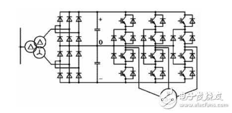
Korlen electric also provide Miniature Circuit Breaker /MCB. Residual Current Circuit Breaker /RCCB. RCBO. Led light and so on .