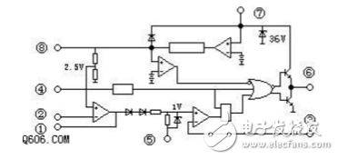
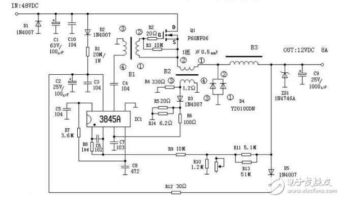
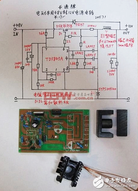
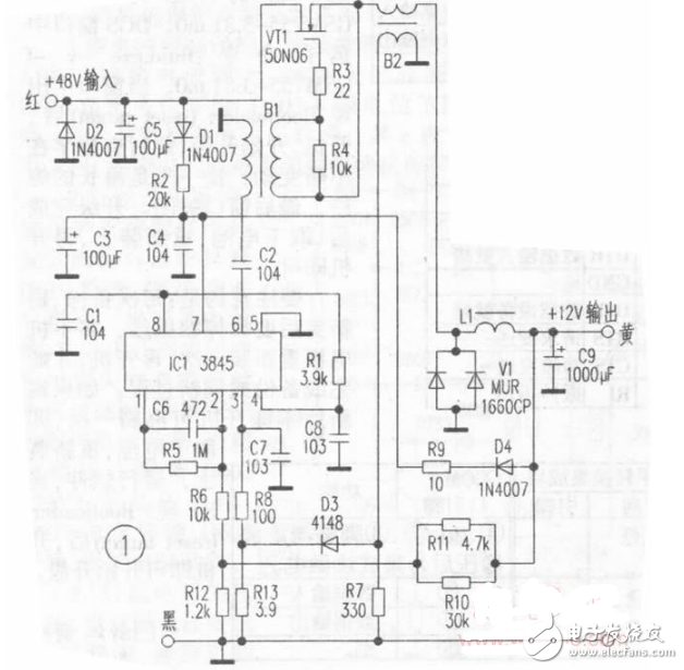
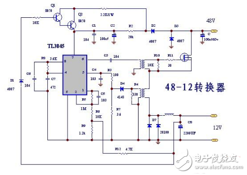
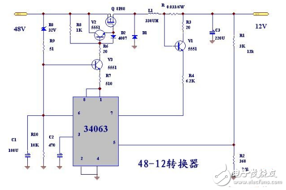
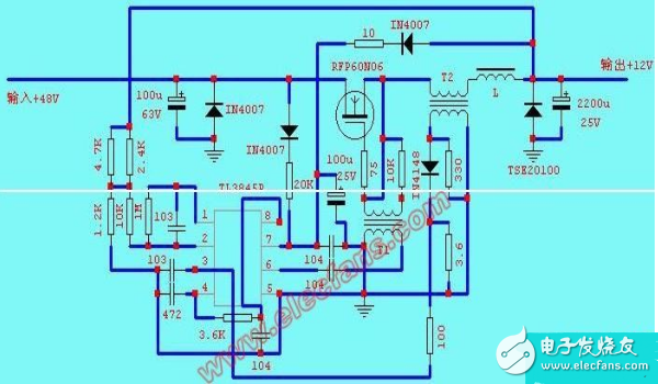
This figure is based on physical analysis. The power supply provides a voltage of about +12V for IC1 through D2 and R1. The output pulse of 6 pin drives Q1 oscillation after coupling with C4 and transformer. When Q1 is turned on, the output current passes through L filter after C9. Power is supplied to the load. When Q1 is cut off, the magnetic energy of the transformer-type inductor B3 is converted into electric energy, the polarity of which is left-right and right-right, and the free-wheeling diode D4 is turned on. The current continues to supply power to the load through the diode, so that the load obtains a smooth DC when the output When the voltage is too low or too high, the sampling voltage is obtained from the voltage dividing circuit composed of the resistors R11, R10, and R9, and is sent to the IC12 pin to compare with the internal 2.5V reference voltage to control the Q1 conduction pulse width, thereby stabilizing the output voltage. When the load current is short-circuited or exceeds 8A, the rise of IC13 pin voltage will control the pulse width to make Q1 cut off to ensure the safety of Q1. C8 and R7 constitute the oscillation time constant. The oscillation frequency of this circuit is 65KHz. The calculation formula is as follows: 3845 internal structure and pin function 1 error amplifier output / compensation 2 voltage feedback input 3 current sampling input 4 oscillator circuit time constant 5 ground 6 switch tube drive pulse output 7 power supply 85V reference voltage is generally connected to the oscillator. The electric vehicle uses 48V to 12V power supply circuit diagram, the input voltage range is 36V to 48V. The maximum current can reach 10a. For electric vehicles, the 48V/12V DC converter is designed to power the entire vehicle lighting and signal. Its voltage output is for headlight illumination (12V/35W), turn signal (12V/8W&TImes; 2) and speaker (12V/). 36W) designed separately or used together, and can protect the load overload. The working principle diagram is shown in Figure 1, and Figure 2 is the printed board diagram. Working principle: 48V voltage provides working voltage for IC1 through D1 and R2, and 10,000-wave pulse output from IC16 pin is converted into pure AC signal by C2 and B1 to provide excitation signal for VT1. When there is no load, the voltage enters the Ic12 pin through R10 and R11. Because the voltage is too high, the output pulse width of the lc16 pin is extremely narrow, and the output terminal voltage is still stabilized at 12V. When there is load, the load and R10 and R11 form a voltage dividing circuit. The voltage entering the IC12 pin changes with the size of the load, so that the output pulse width of the Ic16 pin changes, which serves the purpose of voltage regulation. In addition, when the output current is too large to exceed the limit value, the voltage induced by B2 enters the Ic13 pin through D3 and R8, forcing IC1 to stop vibrating, and protecting VT1 from damage due to overcurrent.
External Cable Assembly Wire:It is used to transmit data, audio, video, etc. it is a kind of electric energy or signal transmission device, which is usually composed of several wires or groups of wires.
External cable assembly line: used for connection, conduction, current and signal transmission of machine equipment, instrument, electronic and electrical peripheral equipment
External Cable Assembly Wire ShenZhen Antenk Electronics Co,Ltd , https://www.antenkcon.com
48v to 12v converter circuit diagram (five 48v to 12v converter circuit schematic diagram)
48v to 12v converter circuit diagram (a) working principle: