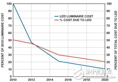
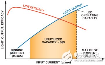
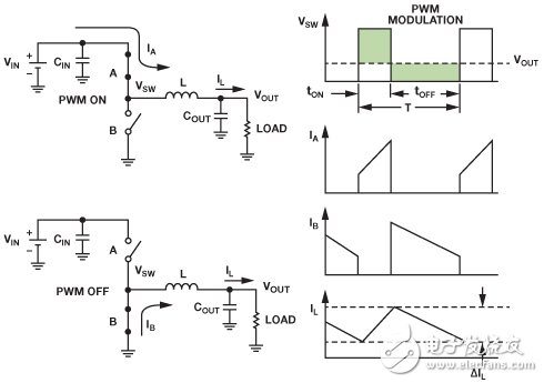
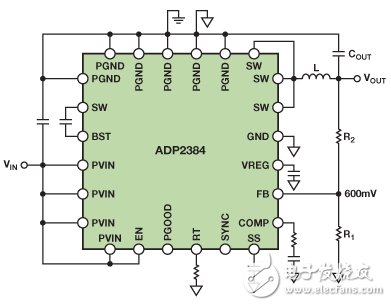
With the advantages of long service life and low power consumption, LED is expected to change the entire lighting industry, but the main obstacle to its rapid adoption is the high cost of LED itself. The cost of LED luminaires (complete electric lighting equipment) varies, but the cost of LEDs usually accounts for about 25% to 40% of the cost of the entire luminaire, and it is expected that it will still account for a high proportion in the coming years (Figure 1). Figure 1. Breakdown of LED lamp cost One way to reduce overall luminaire cost is to drive LEDs at the highest possible DC current within the range allowed by product specifications. This current may be much higher than its "binary current". If driven normally, this may result in a higher lumen / cost ratio. Figure 2. LED light output and efficiency versus drive current However, this approach requires higher current drivers. Many solutions drive LEDs at low current (<500 mA), but few high current (700 mA to 4 A) options. This phenomenon seems surprising, because the semiconductor industry has a large number of DC-DC solutions with a capacity of 4 A, but their design purpose is to control the voltage, not the LED current. This article will discuss some simple techniques for converting off-the-shelf DC-DC buck regulators into smart LED drivers. The buck regulator chops the input voltage and transmits it through the LC filter to provide a stable output, as shown in Figure 3. It uses two active components and two passive components. The active components are the switch "A" from the input to the inductor, and the switch (or diode) "B" from the ground to the inductor. The passive components are the inductor (L) and the output capacitor (COUT). They form an LC filter, which can reduce the ripple generated by the active components. Figure 3. Basic buck solution If the switch is internal, the buck is called a voltage regulator. If the switch is external, it is called the controller. If both switches are transistors (MOSFET or BJT), it is synchronized. If the bottom switch is Implemented using a diode, it is asynchronous. These types of buck circuits have their own advantages and disadvantages, but synchronous buck regulators can usually optimize efficiency, number of devices, solution cost, and board area. Unfortunately, synchronous buck regulators used to drive high current LEDs (up to 4 A) are few and expensive. This article uses ADP2384 as an example to show how to modify the connection of a standard synchronous buck regulator to regulate the LED current. The ADP2384 high-efficiency synchronous buck regulator specifies an output current of up to 4 A with an input voltage of up to 20 V. Figure 4 shows the normal connections used to regulate the output voltage. Figure 4. Connecting the ADP2384 used to regulate the output voltage Closed Tricycle Electric Vehicle Three-Wheel Electric,Enclosed Electric Vehicle,Three-Wheeled Electric Vehicle,Closed Tricycle Electric Vehicle Jinan Huajiang environmental protection and energy saving Technology Co., Ltd , https://www.hjnewenergy.com