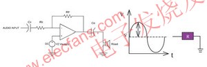
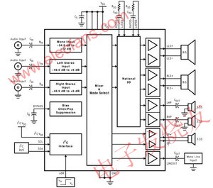
This article is to discuss the application and design of audio systems in mobile phones and PDAs, so that system and R & D personnel can design products suitable for consumers. Considerations for the application of wireless portable electronic products The following lists the main factors that must be considered when selecting an audio power amplifier. High power supply voltage suppression (Power Supply RejecTIon RaTIon; PSRR) The audio power amplifier must have a high PSRR to avoid interference from power supply and wiring noise. Fast turn on & off With a long standby time, it is the basic demand of mobile phones or PDAs. The efficiency of Class AB audio amplifiers is about 50 to 60%, and the efficiency of Class D audio amplifiers can reach 85 to 90%. No matter what kind of audio amplifier is used, in order to save For power consumption, when an audio amplifier is not needed, it is necessary to enter the standby state. However, when a sound appears, the audio amplifier must be turned on immediately. No "Click & Pop" sound The "switching noise" sound often appears when the audio amplifier enters the switch, or returns to normal from standby, or even when the 217Hz mobile phone communication signal, users of mobile phones or PDAs never want to hear disturbing noises. Adding the "switching noise" cancellation circuit to the consideration of audio amplifiers is an important prerequisite. Lower operating voltage In order to prolong the battery life, it is required to work under the condition of as low as 1.8 volts. Low current consumption and high efficiency The use of CMOS process IC can reduce current consumption, sometimes need to choose Class D audio amplifier, the purpose is to extend the working time of mobile phones or personal digital processors. High output power Under the same operating voltage, it has a higher output power, that is, the closer the swing of the output signal is to Vcc and GND, the higher the output power. Smaller package (Micro SMD) The appearance of mobile phones or personal digital processors is getting smaller and smaller, making IC packaging technology more and more important. Micro SMD is a packaging technology that is more commonly used today. Calculation of output power Single-end (Single-end) amplifier as shown in (Figure 1), its gain is: (Formula 1) Gain = Rf / Ri Rf: feedback impedance Ri: input impedance (Figure 1) Single-end (Single-end) amplifier The output power = (VRMS) 2 / Rload, VRMS = Vpeak / 21/2, so the output power of the single-ended (Single-end) amplifier = (Vpeak) 2 / 2Rload. As shown in (Figure 2), the bridge-type (BTL) amplifier is composed of two single-ended (Single-end) amplifiers with a 180 ° difference, so its gain is (Formula 2) Gain = 2Rf / Ri Rf: feedback impedance Ri: The input impedance is output power = (VRMS) 2 / Rload, bridge type VRMS = 2Vpeak / 21/2, so bridge type output power = 2 (Vpeak) 2 / Rload = 4 × terminal amplifier output power Figure 2) The bridge amplifier and the waveforms applied to the positive and negative ends of the speaker Selection of input and output coupling capacitor values As shown in Figure 1, the input impedance and input coupling capacitor form a high-pass filter. If you want to get a lower frequency response, you need to choose a larger capacitor value. The relationship can be expressed by the following formula: (Formula 3) fC = 1/2 ∠(RI) (CI) fC: high-pass filter cut-off frequency RI: input impedance CI: input coupling capacitor value, this capacitor is used to block DC voltage and couple the input signal to the input terminal of the amplifier. In mobile communication systems, due to volume limitations, even with a large input coupling capacitor value, the speaker usually cannot show a frequency response below 50 Hz. Therefore, assuming that the input impedance is 20K ohms, only the input coupling capacitor value is greater than 0.19uF, in this case, 0.22uF is the most appropriate choice. For the setting of the output coupling capacitor value, as in Figure 1, if you want to get a better frequency response, the capacitor value also needs to choose a larger value. The relationship can be expressed by the following formula: (Formula 4) fC = 1 / 2∠(RL) (CO) fC: high-pass filter cut-off frequency RL: impedance of the speaker (headphone) C output coupling capacitance value For example, when using a 32 ohm headphone, if you want to get a frequency response of 50 Hz, you need to select an output coupling capacitor value of 99 uF. In this case, 100 uF is the most appropriate choice. Thermal considerations When designing a single-end (Single-end) amplifier or a bridge-type (BTL) amplifier, power consumption is one of the main considerations. To increase the output power to the load, its internal power consumption also increases. The power consumption of a bridge-type (BTL) amplifier can be expressed by the following formula: (Formula 5) PDMAX_BTL = 4 (VDD) 2 / (2âˆ2RL) VDD: the power supply voltage RL added to the bridge-type (BTL) amplifier: load impedance For example, when VDD = 5V and RL = 8ohm, the power consumption of the bridge amplifier is 634mW. If the load impedance is changed to 32ohm, the internal power consumption is reduced to 158mW. The power consumption of a single-ended amplifier can be expressed by the following formula: (Formula 6) PDMAX_SE = (VDD) 2 / (2âˆ2RL) VDD: the power supply voltage added to the single-ended amplifier RL: The load impedance, that is, the power consumption of the single-ended amplifier is only a quarter of that of the bridge amplifier. The sum of all power consumption divided by the thermal resistance of the IC (? JA) is the temperature rise. Layout considerations There are some basic policies that designers must follow when they are online, for example: All signal lines should be grounded at a single point as much as possible; In order to avoid the mutual interference of the two signals, parallel wiring should be avoided, and the 90 ° crossing method should be used. Digital power and ground should be separated from analog power and ground. High-speed digital signal traces should be away from analog signal traces, and should not be placed under analog components. Application of 3D enhanced stereo in mobile phones and PDA As far as most people understand, "3D sound effect" is neither mono nor bi-channel. It is an audio processing technology that allows the listener to feel the location of the sound in an unrealistic environment. It must be very particular about the placement and number of speakers (speakers). But in mobile phones and PDA processors, so many speakers cannot be placed, so two speakers plus the use of hardware or software to simulate "3D sound effects", also known as "3D enhanced stereo sound effects" ( 3D Enhancement). (Figure 3) is a block diagram of the 3D enhanced stereo sound frequency system used in stereo mobile phones or personal digital processors. This sound frequency system consists of the following parts: Rear amplifier: includes a stereo speaker (speaker) driver, a stereo headphone driver, a mono headphone amplifier (earpiece), and a line out for hands-free handsets, such as hands-free handset phones in automobiles Output. Volume control: Volume control can be divided into 32 levels, and the volume of left, right and mono can be independently controlled. Mixer: used to select the relationship between the output and the input source. It can transmit and mix the stereo and mono inputs together, and divide these inputs into 16 different output modes, allowing system design engineers to flexibly transmit and mix Channel and stereo audio signals, without limiting the signal can only be transmitted to stereo speakers or stereo headphones. Power control and "switching noise" elimination circuit. 3D enhanced stereo, using hardware. Use I2C compatible interface to control the function of the chip. Sound in different positions When it reaches the left and right ears, it will produce different phase differences. Using this phase difference principle and hardware method, 3D enhanced stereo sound effects can be simulated. Even if the system is limited in size or equipment, and the left and right speakers must be placed very close, the positioning of the high and low parts of the stereo can still be improved. Various problems. As shown in the block diagram of the 3D enhanced stereo in Figure 3, an external resistor and capacitor circuit is used to control the sound effect of the 3D enhanced stereo. Two separate resistor and capacitor circuits are used to control the stereo speakers and stereo headphones, which can achieve the best The 3D enhanced stereo effect. In this resistor and capacitor circuit, the "quantity" of the 3D enhanced stereo effect is set by the R3D resistor and is inversely proportional. The C3D capacitor is used to set the 3dB low-frequency cutoff frequency of the 3D enhanced stereo effect. The above can show the 3D enhanced stereo effect, and increasing the C3D capacitor value will lower the low frequency cutoff frequency, and the relationship can be expressed by the following formula. (Formula 7) f3D (-3dB) = 1 / 2∠(R3D) (C3D) (Figure 3) Block diagram of 3D enhanced stereo audio subsystem in conclusion Since mobile phones and personal digital processors have evolved into multi-functional portable devices that can provide various entertainments, manufacturers have tried to adopt highly original audio systems and long-life batteries, and have made such portable electronic devices The product has a stereo speaker amplifier, a variety of different mixing, and 3D enhanced stereo functions. At the same time, the appearance is also as thin and compact as possible. However, its design category still does not deviate from the basic principles mentioned above, which is another purpose of this article. Electrostatic Industrial Exhaust Gas Purifier Electrostatic Air Cleaner,Electrostatic Exhaust Gas Filter,Electrostatic Industrial Exhaust Gas Purifier,Industrial Electrostatic Fume Filter Dongguan V1 Environmental Technology Co., Ltd. , https://www.v1airpurifier.com