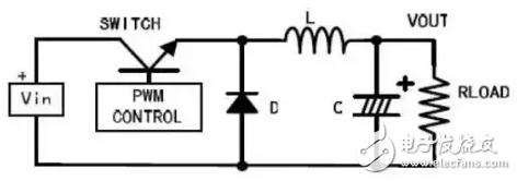
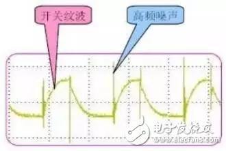
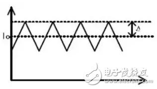
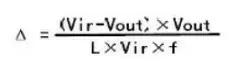
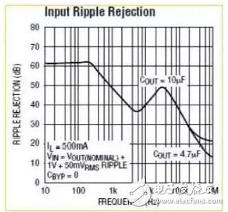
Our ultimate goal is to reduce the output ripple to a level that can be tolerated. The most fundamental solution to this goal is to avoid ripple generation. First, we must understand the type and cause of switching power supply ripple. The picture above is the simplest topology in a switching power supply - the buck step-down power supply. With the SWITCH switch, the current in the inductor L also fluctuates around the effective value of the output current. Therefore, there will also be a ripple at the same frequency as the SWITCH at the output. Generally speaking, the ripple refers to this. It is related to the capacity of the output capacitor and the ESR. This ripple has the same frequency as the switching power supply and is tens to hundreds of KHz. In addition, SWITCH generally uses bipolar transistors or MOSFETs, whichever is the case, there will be a rise and fall time when it is turned on and off. At this time, there will be a noise in the circuit that is the same as the frequency of the SWITCH rise and fall time or an odd multiple, usually tens of MHz. Similarly, diode D is in the reverse recovery moment, and its equivalent circuit is a series connection of resistors, capacitors and inductors, which will cause resonance and generate noise. The frequency is also several tens of MHz. These two kinds of noise are generally called high frequency noise, and the amplitude is usually much larger than the ripple. In the case of an AC/DC converter, in addition to the above two kinds of ripple (noise), there is AC noise, and the frequency is the frequency of the input AC power source, which is about 50 to 60 Hz. There is also a common mode noise due to the equivalent capacitance generated by the power devices of many switching power supplies using the case as a heat sink. basic requirements: AC oscilloscope coupling 20MHz bandwidth limit Unplug the ground wire of the probe 1, AC coupling is to remove the superimposed DC voltage to get an accurate waveform. 2, open the 20MHz bandwidth limit is to prevent high-frequency noise interference, to prevent the detection of erroneous results. Because the high frequency component has a large amplitude, it should be removed when measuring. 3. Unplug the grounding clamp of the oscilloscope probe and measure it with a grounding ring to reduce interference. Many departments do not have a grounding ring, and if the error allows, it is also measured directly with the grounding clamp of the probe. However, this factor should be considered when judging eligibility. Another point is to use a 50? terminal. According to the Yokogawa oscilloscope data, the 50? module removes the DC component and accurately measures the AC component. However, few oscilloscopes are equipped with this special probe. In most cases, the probe is measured with a standard 100K to 10M?, and the impact is temporarily unclear. The above is a basic precaution when measuring switch ripple. If the oscilloscope probe is not in direct contact with the output point, it should be measured with twisted pair or 50? Coaxial Cable. When measuring high frequency noise, use the oscilloscope's full passband, typically on the order of hundreds of megahertz to GHz. Others are the same as above. Different companies may have different test methods. In the final analysis, you must be clear about your test results. The second is to be recognized by the customer. About the oscture Some digital oscilloscopes cannot properly measure ripple due to interference and memory depth. Replace the oscilloscope at this time. Sometimes, although the old analog oscilloscope has a bandwidth of only a few tens of megabytes, it performs better than a digital oscilloscope. Switching power supply ripple rejection For switching ripple, both theoretically and practically there must be. There are three ways to suppress or reduce it: 1, increase inductance and output capacitance filtering According to the formula of the switching power supply, the current fluctuation in the inductor is inversely proportional to the inductance value, and the output ripple is inversely proportional to the output capacitance value. Therefore, increasing the inductance value and output capacitance value can reduce the ripple. The figure above shows the current waveform in the inductance L of the switching power supply. The ripple current ΔI can be calculated by the following equation: It can be seen that increasing the L value, or increasing the switching frequency, can reduce current fluctuations within the inductor. Similarly, the relationship between output ripple and output capacitance: vripple=Imax/(Co&TImes;f). It can be seen that increasing the output capacitor value can reduce the ripple. As a general rule, for output capacitors, aluminum electrolytic capacitors are used to achieve high capacity. However, the electrolytic capacitor is not very effective in suppressing high-frequency noise, and the ESR is also relatively large, so a ceramic capacitor is connected in parallel with it to compensate for the shortage of the aluminum electrolytic capacitor. At the same time, when the switching power supply is working, the voltage Vin at the input terminal does not change, but the current varies with the switch. At this time, the input power supply does not provide a good current, usually near the current input terminal (in the case of the BucK type, which is near SWITcH), and a parallel capacitor is used to supply current. After applying this countermeasure, the BUCK type switching power supply is as shown below: The above approach has a limited effect on reducing ripple. Because of the volume limitation, the inductance will not be very large; the output capacitance will increase to a certain extent, and there is no obvious effect on reducing the ripple; increasing the switching frequency will increase the switching loss. So when the requirements are strict, this method is not very good. Regarding the principle of the switching power supply, etc., reference can be made to various switching power supply design manuals. 2, secondary filtering, is to add a primary LC filter The LC filter suppresses the noise ripple significantly. Selecting the appropriate inductor and capacitor according to the ripple frequency to be removed constitutes the filter circuit, which can generally reduce the ripple. However, in this case, it is necessary to consider the sampling point of the feedback comparison voltage. (As shown below) The sampling point is selected before the LC filter (Pa) and the output voltage is reduced. Because any inductor has a DC resistance, when there is a current output, there will be a voltage drop across the inductor, causing the output voltage of the power supply to drop. And this voltage drop is a function of the output current. The sample point is selected after the LC filter (Pb) so that the output voltage is the voltage we want. However, this introduces an inductor and a capacitor inside the power system, which may cause system instability. Regarding the stability of the system, a lot of information has been introduced, and it is not written in detail here. 3, after switching power supply output, connect LDO filter This is the most effective way to reduce ripple and noise. The output voltage is constant and there is no need to change the original feedback system, but it is also the most costly and power consuming method. Any LDO has an indicator: the noise suppression ratio. Is a frequency-dB curve, as shown on the right is the curve of the Linear Technology LT3024. After the LDO, the switching ripple is generally below 10mV. The figure below shows the ripple contrast before and after the LDO: Comparing the curve on the graph above and the waveform on the left, it can be seen that for a few hundred KHz switching ripple, the suppression effect of LDO is very good. But in the high frequency range, the effect of the LDO is not so good. For reducing ripple. The PCB layout of the switching power supply is also very critical, which is a very difficult problem. There are special switching power supply PCB engineers. For simple reference, please refer to AN1229: SIMPLE SWITCHER PCB Layout Guidelines of US National Semiconductor Corporation. For high-frequency noise, although the frequency is high, the post-stage filtering has a certain effect, but the effect is not obvious. There is a special study in this area. The simple method is to use a capacitor C or RC or a series inductor on the diode. 4, on the diode and capacitor C or RC The figure above is the equivalent circuit of the actual diode. Parasitic parameters should be considered when the diode is turned on and off at high speed. During diode reverse recovery, the equivalent inductance and equivalent capacitance become an RC oscillator, producing high frequency oscillations. In order to suppress this high frequency oscillation, a capacitor C or RC buffer network is connected in parallel across the diode. The resistance is generally 10Ω-100 Ω, and the capacitance is 4.7pF-2.2nF. The capacitance C or RC connected in parallel on the diode is determined by trial and error. If improperly chosen, it will cause more serious oscillations. For high frequency noise requirements, soft switching technology can be used. There are many books devoted to soft switches. 5, the diode is followed by the inductor (EMI filter) This is also a common method of suppressing high frequency noise. Selecting a suitable inductive component for the frequency at which noise is generated can also effectively suppress noise. It should be noted that the rated current of the inductor should meet the actual requirements. The simpler approach is not explained in detail. The above is about switching power supply ripple, summed up some content, if you can add some waveforms is better. Although it may not be complete, it is enough for general applications. Regarding noise suppression, not all of them are actually applied. It is important to choose the appropriate method according to your own design requirements, such as product volume, cost, development cycle, etc. Speaker Cables,Speaker Cable To Rca,Speaker Cable Types,Speaker Cable Connectors CHANGZHOU LESEN ELECTRONICS TECHNOLOGY CO.,LTD , https://www.china-lesencable.com Switching power supply ripple generation
Switching power supply ripple measurement


summary
These techniques make the development of high-reliability embedded systems easier
0 times
Window._bd_share_config = { "common": { "bdSnsKey": {}, "bdText": "", "bdMini": "2", "bdMiniList": false, "bdPic": "", "bdStyle": " 0", "bdSize": "24" }, "share": {}, "image": { "viewList": ["qzone", "tsina", "tqq", "renren", "weixin"], "viewText": "Share to:", "viewSize": "16" }, "selectShare": { "bdContainerClass": null, "bdSelectMiniList": ["qzone", "tsina", "tqq", "renren" , "weixin"] } }; with (document) 0[(getElementsByTagName('head')[0] || body).appendChild(createElement('script')).src = 'http://bdimg.share. Baidu.com/static/api/js/share.js?v=89860593.js?cdnversion=' + ~(-new Date() / 36e5)];