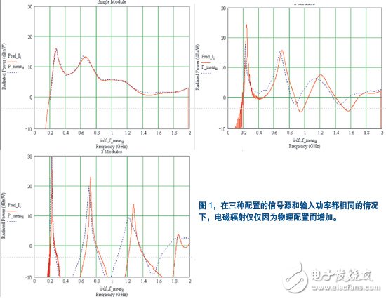
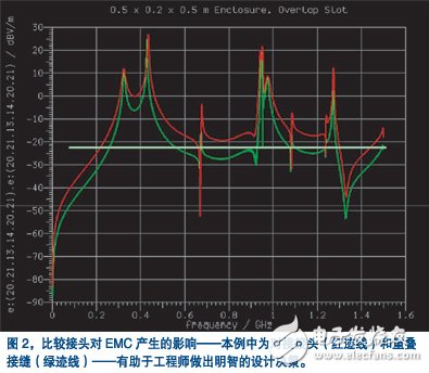
Higher clock rates increase the difficulty of meeting electromagnetic compatibility requirements. In the gigahertz field, an increase in the number of resonances in the enclosure enhances electromagnetic radiation, making apertures and gaps a problem; application-specific integrated circuit (ASIC) heat sinks also increase electromagnetic radiation. In addition, regulatory agencies are developing regulations to ensure compliance at increasingly higher frequencies. Furthermore, when engineers plan to design radiators into their systems, they pose further challenges to the trend of integrated wireless functions such as Wi-Fi, Bluetooth, WiMax, and UWB. Under normal circumstances, electrical hardware designers and mechanical designers are independent when considering electromagnetic compatibility issues, and do not communicate or communicate with each other at all. They often use rules of thumb during design, and hope that these rules are sufficient to meet the device requirements of their design. Many of these EMC design rules become obsolete when the design reaches a higher frequency and causes failures in the test. After the design phase, the designer made the prototype and tested it for electromagnetic compatibility. When electromagnetic compatibility is considered too late in the design, this process often has various EMC problems. Expensive repairs to designs are often the only viable option. Design changes often increase by more than an order of magnitude as the design moves from system concept design to specific design to verification. Therefore, a modification to the design will cost only $100 in the conceptual design phase, and it may cost hundreds of thousands of dollars in the testing phase, not to mention the negative impact of the opposite market time. In order to pass electromagnetic compatibility testing in the laboratory and ensure on-time delivery within budget, it is necessary to make EMC design an integral part of the product's production cycle. Designers can do this with the help of the 3D solution of Maxwell's equations. Maxwell's equation is a concise mathematical expression of electromagnetic interaction. However, electromagnetic compatibility simulation is a problem that is not common in other fields of computational electromagnetics. Typical EMC issues are related to the enclosure, which has a greater impact on EMC than slots, holes, and cables that are important to EMC performance. Accurate modeling requires that the model contain large and small details. This requirement results in a large aspect ratio (the ratio of the largest feature size to the smallest feature size), which in turn requires a fine grid to resolve the finest details. Compression model technology allows you to include structures large and small in your simulation without excessive simulations. Another challenge is that you must complete the characterization of EMC over a wide frequency range. The time required to calculate an electromagnetic field at each sampling frequency can be prohibitive. Time domain methods such as the Transmission Line Method (TLM) can use the wideband excitation to calculate the electromagnetic field in the time domain so that data for the entire frequency band can be derived in one simulation. The space is divided into cells that are modeled at the intersection of orthogonal transmission lines. Voltage pulses are emitted and scattered at each unit. You can calculate the electric and magnetic fields at regular intervals based on the voltage and current on the transmission line. EMC simulations yield accurate results. Figure 1 compares the radiated power calculations (red) of the three module configurations (ie, 1, 2, and 3 modules) mounted on a backplane with the measured results of the radiated power (blue) (Reference 1) ). The calculated radiated power is based on 1nw in dB. You can attribute small differences in the resonant peak position of multiple module configurations to the difficulty of accurately aligning multiple modules in a measurement. It is worth noting that since the input powers of the three configurations are the same, the difference in the resonance peak and amplitude of the radiated power is only caused by the difference in system layout. EMC simulation can be used to detect components and subsystems, such as the radiation distribution of the heat sink ground to the frequency characteristics, and can also be used to evaluate grounding techniques, the effects of heat sink shapes, and other factors. In addition, you can compare the size and shape of different vents and the shielding effect of metal thickness. One of the latest applications in this field is to evaluate the use of large-diameter vents for air supply and to achieve shielding by placing two back-to-back spaced panels. EMC simulation is also suitable for system-level EMC design and optimization to calculate broadband shielding effects, broadband electromagnetic radiation, 3-D far-field radiation patterns, cylindrical near-field electromagnetic radiation used to simulate rotary measurements, and for visualization To help determine the current and electromagnetic field distribution at the EMC hotspot location. Typical system-level EMC applications are: enclosure design to ensure maximum shielding, EMC performance evaluation of component placement within the enclosure, calculation of cable coupling inside and outside the system, and detection of cable radiation effects. EMC simulation also helps to discover the mechanisms of unwanted electromagnetic waves in the chassis and subsystems, such as cavity resonance, electromagnetic radiation through holes, slots, seams, and other base openings, conducted radiation through the cable, and Coupling of heat sinks, other components, and parasitic waveguides inherent to optical components, displays, LEDs, and other components mounted on the base. You can use a simple and fast-built case model for design trade-offs in seam configuration. Figure 2 provides an assessment of the radiation produced by the butt joint and the radiation produced by the overlapping shell seams. By comparing the relative shielding levels, engineers can make decisions based on the chassis' EMC budget and the cost of implementing a specific design configuration. The addition of internal components during the simulation process has only a small effect on the simulation time, so the designer can easily perform the joint shielding effect in the real environment that causes the coupling between the cavity resonance, the cavity mode and the interaction with the internal structure. Evaluation. The design rules for slot leakage do not apply to the above factors, resulting in costly over design and under design.
Intel I5 Laptop is the one of the important high cpu processors, another ones are i3, i7, i9. We can do 2th, 4th, 5th, 6th, 8th, 10th, 11th or 12th. How to choose a best suitable one? If you do heavier jobs, like interior design, music or video editing, even engineering drawing, etc, 15.6 inch Intel I5 11th Generation Laptop or Intel I5 10th Generation Laptop is a better choice for you. If you focus on portability, Laptop 14 Inch I5 11th generation is a good option. Of course, Intel i7 11th Generation Laptop or 1650 graphics card laptop also available.
Someone may worry the custom one quality, that`s cause that lack of custom Student Laptop knowledge, so just keep reading so that know deep in this field. Frankly speaking, the technical skill is totally mature, no matter hardware or software or craft. You can see nearly no difference when check the oem laptop and brand one in person. To support clients and be confident with our product, provide sample for every clients.
Any other special requirements, you can just contact us freely or email us and share the exact details about what you need, thus right and valuable information sended in 1 working day.
Intel I5 Laptop,Intel I5 11th Generation Laptop,Intel I5 10th Generation Laptop,Laptop 14 Inch I5,Intel I5 Laptop Price Henan Shuyi Electronics Co., Ltd. , https://www.shuyicustomtablet.com As product complexity and density increase and design cycles continue to shrink, it becomes increasingly impractical to address electromagnetic compatibility (EMC) issues later in the design cycle. At higher frequencies, the rules of thumb that you usually use to calculate EMC no longer apply, and you may be able to misuse these rules of thumb. As a result, 70% to 90% of new designs have not passed the first EMC test, which makes the late redesign cost very high. If the manufacturer delays the product delivery date, the lost sales cost will be even greater. In order to identify and solve problems at a much lower cost, designers should consider adopting collaborative, concept-based EMC simulations early in the design process.