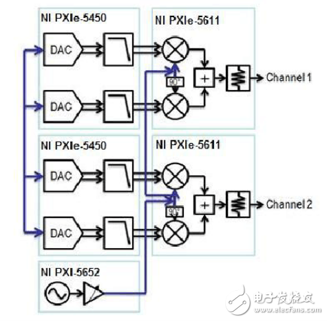
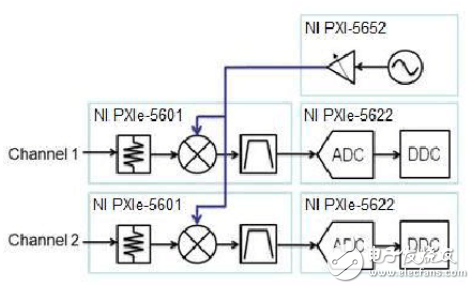
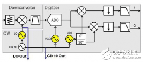
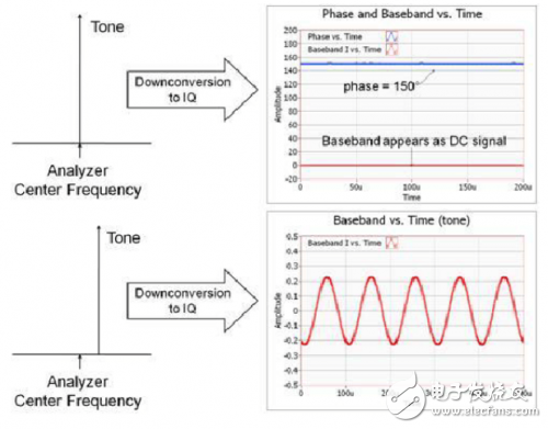
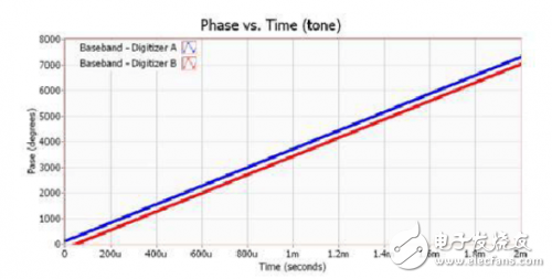
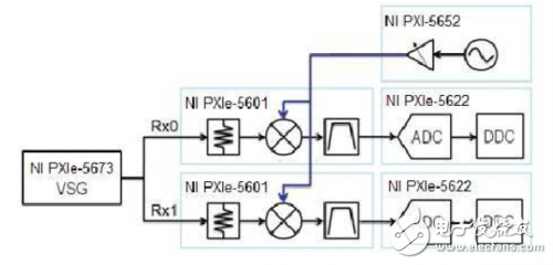
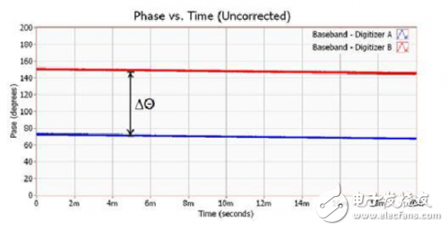
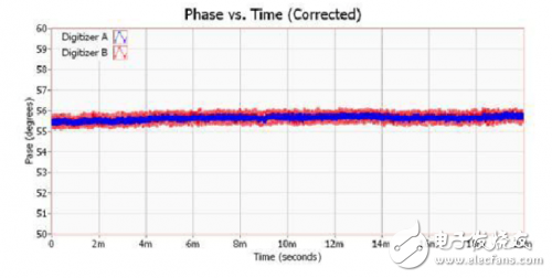
Since the first radio wave was transmitted, engineers have continued to invent new methods to optimize electromagnetic microwave signals. RF signals have been used in a wide variety of applications, and this common technology is being exploited in two special applications for wireless communications and RADAR. In essence, the uniqueness of these two applications is the use of the spatial dimension of the electromagnetic wave (SpaTIal dimension). To date, many wireless communication systems have integrated multiple input/output (MIMO) antenna architectures to take advantage of the multipath signal propagation (PropagaTIon) functionality. In addition, many RADAR systems currently use Beam steering to replace traditional mechanically controlled transmission signals. These applications are among the main driving forces of the multi-channel phase coherent RF measurement system. In essence, the uniqueness of these two applications is the use of the spatial dimension of the electromagnetic wave (SpaTIal dimension). To date, many wireless communication systems have integrated multiple input/output (MIMO) antenna architectures to take advantage of the multipath signal propagation (PropagaTIon) functionality. In addition, many RADAR systems currently use Beam steering to replace traditional mechanically controlled transmission signals. These applications are among the main driving forces of the multi-channel phase coherent RF measurement system. The modular architectures of PXI RF instruments (such as the NI PXIe-5663 6.6 GHz RF vector signal analyzer and NI PXI e-5673 6.6 GHz RF vector signal generator) modulation architecture for MIMO and beamforming (Beamforming) Apply the required phase coherent RF measurement operation. Figure 1 shows a common measurement system with four sets of synchronized RF analyzers in a set of PXI-1075 - 18-slot chassis and two sets of synchronized RF signal generators. Figure 1. Common PXI Phase Coherent RF Measurement System This technical document will describe the techniques required to set up a phase-coherent RF generation or capture system. In addition, calibration operations will be presented step by step for phase delays between multiple RF analyzers for optimal performance. To set up any phase coherent RF system, all frequency signals of the device must be synchronized. With the NI PXIe-5673 - 6.6 RF vector signal generator, Upconversion can be directly converted to compile the Baseband waveform into an RF signal. Figure 2 illustrates the basic architecture of a two-channel RF vector signal generator. Please note that 2 sets of fundamental frequency sampling frequency and local oscillator must be shared between 2 channels. Figure 2. Synchronizing 2 RF generation channels In Figure 2, the NI PXIe-5673 is available in three modules: the PXI-5652 Synthesizer, the PXIe-5450 Arbitrary Waveform Generator, and the PXIe-5611-RF Modulator. Since these modules can be combined as a single-channel RF vector signal generator, other arbitrary waveform generators (AWGs) and RF converters (Upconverters) can be integrated for multi-channel signal generation applications. In Figure 2, there is a standard set of PXIe-5673 (consisting of 3 modules) that integrates a set of NI PXIe-5673 MIMO expansion combinations. The expansion combination accommodates a set of AWGs and modulators to construct a second signal generation channel. In addition to the PXIe-5673 - RF vector signal generator, the PXIe-5663 - RF vector signal analyzer can also be configured for multi-channel applications. When setting up multiple sets of PXIe-5663 for phase-coherent RF signal acquisition, you must also pay attention to similar matters to ensure the synchronization of LO and fundamental/intermediate frequency (IF) signals. The PXIe-5663 can be converted to IF using the Signal stage and down converted to a base frequency. Unlike the traditional 3-stage Superheterodyne vector signal analyzer, this architecture only needs to synchronize a single local oscillator (LO) between channels, so it is the easiest to set phase coherence applications. One of the methods. To synchronize multiple sets of PXI-5663 analyzers, a shared IF sampling frequency and LO must be assigned between each set of analyzers to ensure that each channel is set in phase coherence. Figure 3 shows an example of a two-channel system. Figure 3. Synchronized dual channel VSA system In Figure 3, the PXIe-5663 - RF vector signal analyzer is composed of a PXI-5652 continuous wave synthesizer, a PXIe-5601 - RF down converter, and a PXIe-5622 - IF oscilloscope. When the Vector Signal Analyzer integrated the PXIe-5663 MIMO expansion combination, a new down converter and oscilloscope was added to construct a dual channel RF capture system. To understand the synchronization of multiple sets of RF vector signal analyzers, you must first dive into the detailed program diagram of the PXIe-5663 - RF Signal Analyzer. As you can see in Figure 4, even if only a single LO is used to convert the RF down to IF, each group of analyzers must actually share three sets of frequencies. Figure 4. Detailed schematic of the PXIe-5663 - RF Vector Signal Analyzer As shown in Figure 4, the LO, ADC sampling frequency, digital down converter (DDC), and numerically controlled oscillator (NCO) must be shared between the RF channels. As you can see in Figure 4, even sharing 10 MHz between groups of oscilloscopes is extremely good. When only 10 MHz reference is shared between each group of oscilloscopes, uncorrelated channel-to-channel phase jitter can be generated; the phase noise intensity generated by IF will also be covered by RF LO phase noise. Before understanding the exact calibration method of the phase-coherent RF acquisition system, you must first understand how the RF signal characteristics should be observed at the fundamental frequency. Here, the VSG and VSA set at the same center frequency and in the loopback mode are taken as an example. As shown in Figure 5, the down-converted RF signal with the center frequency of the analyzer is presented as a DC signal based on the fundamental frequency. In addition, since the fundamental frequency signal is a complex waveform, the phase (Θ) of the signal can also be analyzed as a time function. As can be seen in Figure 5, as long as the RF vector signal generator and the analyzer are in-phase with each other, the "Phase vs. time" waveform will exhibit a stable phase offset. Figure 5. Understanding the effects of the fundamental frequency offset Relatively speaking, as long as the RF tone (Tone) and the analyzer's center frequency produce small errors, it can make a huge difference. When the down conversion is converted to the fundamental frequency, the fundamental frequency I (also Q) signal generated by the Offset tone is a sine wave. In addition, the frequency of the fundamental frequency sine wave is equal to the "frequency difference between the input pitch and the center frequency of the analyzer". Therefore, as shown in Figure 6, the "Phase versus time" graph will exhibit a linear relationship. Figure 6. 10 MHz tone "Phase vs. Time" diagram in an uncalibrated system From Figure 6, it can be seen that the phase is located in each microsecond (Microsecond) can increase nearly 360 – that is, the generated pitch and the center frequency of the analyzer, which can be exactly 1 MHz offset. It can also be seen in Figure 6 that there is a very small but stable phase difference between the two sets of simultaneous sampling oscilloscopes. This discrete phase difference is due to the difference in length of the connection between the LO supply to each group of down converters. As will be seen next, calibration can be easily performed by adjusting the start phase of the DDC for one of the RF channels. As shown in Figure 7, one of the precise ways to measure the phase shift between two sets of analyzers is to generate a single tone at the center frequency of the two sets of analyzers. Figure 7. Calibration test setup for dual channel RF analyzer phase The "Phase versus time" of each group of analyzers can be measured by the splitter and the corresponding length of the cable. Assuming that both the signal generator and the analyzer are concentrated at the same RF frequency, the "Phase versus time" graph for each group of analyzers is found to be very consistent. Figure 8 shows this state. Figure 8. Each group of simultaneously sampled ADCs will have the same phase offset It is evident from Figure 8 that two sets of analyzers sharing the same LO and IF sampling frequency will maintain a stable phase offset. In fact, the phase difference between each group of analyzers (∆Θ = 71.2° in Figure 8) can be measured and compensated. To compensate for the phase difference between the various sets of analyzers, you only need to adjust the start phase of the NCO in the DDC. If the IF center frequency used by the NCO is used to generate the final baseband I and Q signals, then this NCO is essentially a digital sine wave. In Figure 8, it can be seen that an RF analyzer connected in a Daisy-chained manner can generate a carrier phase difference of 71.2° through a specific center frequency. After integrating the length of the second set of LOs and the center frequency used, the exact phase offset can be determined. If the 71.2° phase delay is applied to the NCO of the main DDC, the fundamental signal phase of the two channels can be easily adjusted; as shown in Figure 9. Figure 9. Phase-aligned RF after calibration. Capture channel "Phase vs. Time" Once the NCO of each set of analyzers is calibrated, the RF analyzer system can perform phase coherent RF capture operations for more than 2 channels. In fact, multi-channel applications can synchronize up to four PXIe-5663 - RF vector signal analyzers. While MIMO and beamforming technologies are booming, they also present new challenges for test engineers; and modular RF instrumentation provides a cost-effective and accurate measurement solution. Further, PXI instruments such as the PXIe-5663 VSA and PXIe-5673 can be configured for applications up to 4x4 MIMO and phase coherent RF measurements.
Flat Control Cable Also known as festoon cable, this flat cable fits in confined spaces such as overhead cranes and hoists. It sends signal and data to operate, measure, or regulate automated equipment.
Raw cable can be UL2651, UL20251 ,etc
Flat cable, IDC cable, flat cable wiring, ribbon cable harness, flexible flat cable ETOP WIREHARNESS LIMITED , https://www.wireharness-assembling.com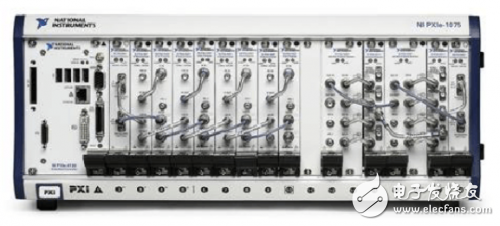
Set phase coherence RF measurement system: detailed tutorial from MIMO to beamforming
Overview