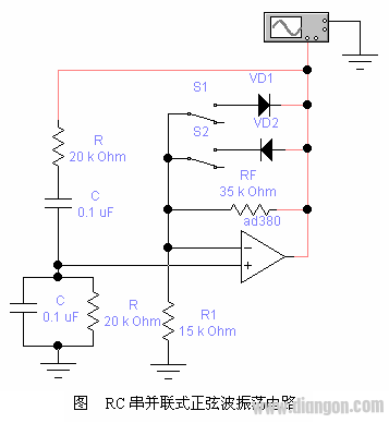
Experimental content: 1. Observe the starting condition (1) Settings , Observe the output waveform, no waveform - no vibration. (2) Design at this time, , Observe the output waveform, there is a waveform - start-up; Increase Observe the output waveform starting condition - the starting speed is fast, but the waveform is distorted. in conclusion: a. , can't shake; , can start vibration; start condition: . b. The larger, the easier it is to start, the worse the waveform. 2. Improve the waveform Connect VD 1 and VD 2 to increase the amplitude stabilization circuit and observe the output waveform – the distortion is reduced. in conclusion: Adding a diode stabilization circuit improves the waveform. 3. Measurement frequency Measured value: period T = 12.99ms, frequency f = 76.98Hz Calculated value: frequency Blank Patch Panel,1U 12 24 Port Blank Patch Panel,Keystone Patch Panel Blank Chinasky Electronics Co., Ltd. , https://www.chinacctvproducts.com