0 Preface Medical power is a device with relatively high safety regulations, EMI and EMC. As a green switching power supply, it will bring great changes to human society in the 21st century. A high-performance medical device system is inseparable from a high-performance control module, and the performance of the control module depends to a large extent on the performance of the power supply, so a high-quality power supply system occupies a very important position in the entire medical system. This article is based on the UC3842 high-performance current mode PWM generator controlled switching power supply is suitable for this type of system. The design achieves complete isolation of the output and input through a small high-frequency transformer, which not only improves the efficiency of the power supply, simplifies the peripheral circuit, but also reduces the cost and volume of the power supply. The output voltage of the power supply is stable, the ripple is small, the uninterrupted performance is reliable, and there is no radiation or conduction interference to other equipment. 1 Basic structure of single-ended flyback converter circuit The typical structure of a single-ended flyback transform is shown in Figure 1. Single-ended means that the core of the transformer only works on one side of the hysteresis loop; the flyback means that when the switch is turned on, energy is stored in the primary coil, and the secondary coil is not connected. When the switch is closed, the primary The energy in the coil is released to the load through the secondary coil. This is a low-cost regulator that provides complete isolation of the input and output sections and a good voltage regulation. 2 UC3842 chip performance characteristics The UC3842 chip is a product of Unit Rode. It is a high-performance single-ended output current-controlled pulse width modulator chip. The block diagram is shown in Figure 2. It consists of a 5V reference, an oscillator that controls the duty cycle setting, a current measurement comparator, a PWM latch, a high-gain E/A error amplifier, and a high-current push-pull output circuit for driving the power MOSFET. Its main features are: 1 few external components, simple peripheral circuit, and low price; 2 No need to input transformer, the starting current is small (less than 1mA); 3 has a precise voltage reference source (±1%); 4 high current (1A) PWM output stage, which can directly drive the power MOS tube; 5 has under voltage lockout and over current protection function; 6 working frequency up to 500kHz. The UC3842 chip can be used for low-power switching power supplies of 20 to 80W, because it can meet both good electrical performance and low cost. In Figure 2, pin 8 is its internal reference voltage (5V); pin 7 is its power supply terminal, the chip's working turn-on voltage is 16V, and the undervoltage lockout voltage is 10V; 4 pin is connected to the oscillating circuit to generate the sawtooth wave RT of the desired frequency. Connected between 4 and 8 feet, CT is connected between 4 feet and ground. Pins 1 and 2 are the inverting input of the compensation terminal and the internal voltage comparator. The current feedback signal introduced from pin 3 is compared with the voltage error signal of pin 1 to generate a PWM (pulse width modulation) wave from pin 6 (output). The terminal outputs the signal to control the on and off of the power device. Pin 3 is the current sense input. Since the current comparator input is set with a current clamp of 1V, when the current is too large and the voltage on the current sense resistor R9 (shown in Figure 3) exceeds 1V (that is, the 3-pin level is greater than 1V), it will be turned off. PWM pulse to achieve overcurrent protection. Led Clock,Clock Light,Indoor Wall Light,Table Lamp With Clock Guangzhou Huanyu Clocking Technologies Co., Ltd. , https://www.findclock.com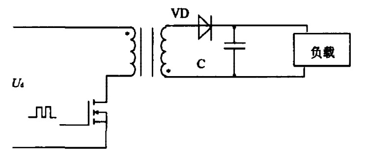
Figure 1 single-ended flyback converter 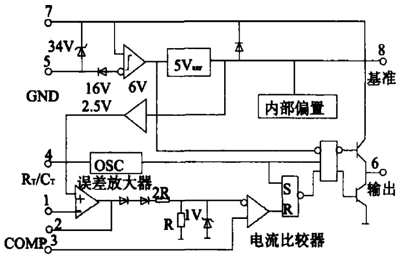
Figure 2 VC3842 block diagram
Medical Switching Power Supply Design Based on PWM Chip (UC3842)
Abstract : Based on UC3842 high-performance current mode PWM chip, a medical switching power supply design scheme is proposed. The AC-DC is designed to supply power to medical equipment. It uses a single-ended flyback structure to achieve 90-264Vac power supply and 12V DC output. It has the advantages of fast transient response, good electromagnetic compatibility, high output voltage accuracy, etc. Medical equipment power supply needs.