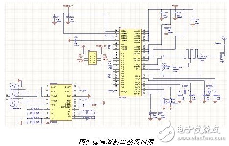
RFID (RadioFrequeneyIdenTIficaTIon) radio frequency identification is a non-contact automatic identification technology. It automatically recognizes the target object and acquires relevant data through radio frequency signals. The identification work can work in various harsh environments without manual intervention. The RFID system is mainly composed of two parts: the reader and the electronic tag. The data is stored in the electronic tag. When the electronic tag enters the effective working distance of the reader, the two parties can communicate according to a certain protocol. RFID technology recognizes high-speed moving objects and recognizes multiple labels at the same time, making operation quick and easy. Short-range RF products are not afraid of harsh environments such as oil stains and dust pollution. Bar codes can be replaced in such environments, such as tracking objects on the assembly line of a factory. Long-range RF products are mostly used for transportation, and the recognition distance can reach several tens of meters, such as automatic charging or identification of vehicle identity [6]. In addition, because the technology is difficult to be counterfeited and invaded, the electronic tag has an extremely high security protection capability. The application of RFID is very extensive. At present, typical applications include animal wafers, automobile chip alarms, access control, parking lot control, production line automation, and material management. Countries and relevant international organizations are actively promoting the development of RFID technology standards. At present, there is no perfect international and domestic standard for RFID. The current major RFID related specifications include the EPC specification in Europe and the United States, the UID (UbiquitousID) specification in Japan, and the ISO 18000 series of standards. There are many types of RFID electronic tags, and the classification methods are various. According to the power supply mode, it can be divided into active and passive electronic tags; according to the carrier frequency, it can be divided into low frequency (134.2kHz), high frequency (13.56MHz), ultra high frequency (433MHz and 915MHz), and microwave electronic tag (2.45GHz). Above) [6]; the single technology of RFID electronic tags has matured, but there are still a lot of technical problems in the practical application of logistics industry and manufacturing industry. Such as: economics, signal interference, improvement of recognition rate, information security and privacy protection, standardization and other issues. The basic RFID system consists of RFID tags (Tags), RFID readers (Reader) and application support software. The CC2430 chip is supported by a powerful integrated development environment. The interactive debugging of internal lines is supported by the IDE's IAR industry standard and is highly recognized by embedded organizations. It is also suitable for devices with a frequency of 2.4 GHz. The CC2430 is fabricated in an O.18μm CMOS process with a current consumption of 27 mA during operation and a current loss of less than 27 mA or 25 mA in receive and transmit modes, respectively. Available in 7 mm & TImes; 7mm QLP package with 48 pins. All pins can be divided into I/O port line pins, power line pins and control line pins [5]. The CC2430's sleep mode and ultra-short-time transition to active mode are ideal for applications that require very long battery life. Particularly suitable for the design of RFID systems. This article uses TI's CC2430 as the core to design active RFID tags. Use 3.3-4. 5V. It can be powered by a button battery and the chip consumes less power. The required peripheral circuits are few, and the high-frequency components are all integrated in the chip, and the working performance is stable without being affected by the outside. Ideal for applications with low power consumption and high performance requirements. 2.1 hardware circuit structure A typical active RFID tag consists of an antenna, a radio frequency module, a control module, a memory, a wake-up circuit, a battery module, etc. as shown in FIG. The radio frequency module completes the modulation and demodulation of the control signal and the response signal between the tag and the reader. The controller executes the instructions of the reader. The memory stores information about the tag and the control program of the microcontroller. The controller reads and writes to the memory. The radio frequency module includes a transmitting portion and a receiving portion. The transmitting part mainly consists of a modulator, a power amplifier, a band pass filter, a mixer and a local oscillator. The receiving part is composed of a low noise amplifier, a band pass filter, a demodulator, and a waveform shaping. TI's CC2430 chip integrates all wireless communication systems and adds a few peripheral circuits to form a wireless communication module, which reduces system cost and simplifies label design. CC2430 chip adopts O. Produced in a 18μm CMOS process, the current consumption is 27 mA during operation; in receive and transmit modes, the current loss is less than 27mA or 25 mA, respectively. Available in a 7 mm x 7mm QLP package with 48 feet. All pins can be divided into three types: I/O port line pins, power line pins, and control line pins. The CC2430's sleep mode and ultra-short-time transition to active mode are ideal for applications that require very long battery life. Particularly suitable for the design of RFID systems. This tag design matches the circuit to match the output to a 50 ohm microstrip patch antenna. Surface-mount components are used in the PCB design, which simplifies the complexity of the system and the size of the label. The entire PCB is controlled in 10CM*5CM, which satisfies the design of the label miniaturization. The circuit diagram of the tag is shown in Figure 2. 2.2 Low Power Design of Labels For active tags, because they are battery powered, the tag's working life is limited, which requires the tag to be energy efficient and its power consumption to be low. Thereby saving the energy of the battery to extend the working life of the label. CC2430 chip adopts O. Produced in a 18μm CMOS process, the current consumption is 27 mA during operation; in receive and transmit modes, the current loss is less than 27mA or 25 mA, respectively. Adding a certain control program during the label design process allows the tag to enter the working state to respond to the reader's query request only within the working range of the reader. Thereby maximizing energy savings. 2.3 reader design Specifications: ethereum miner for sale,mining rig for sale,ethereum mining rig,cryptocurrency mining rigs,buy mining rig Easy Electronic Technology Co.,Ltd , https://www.yxpcelectronicgroups.com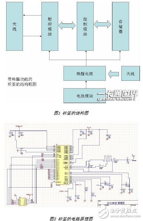
Model: K37-65mm
Color: Green
Material: SECC
Size: 70*40*18cm
Motherboard: K37
CPU: G1820
Memory: 4GB DDR3
Fans: 4*2800RPM turbo fans
Card distance: 65mm
Card slots: 8
Applicable graphics card: GPU P104,GPU P106,GPU 1660,GPU 3060,GPU 3070,GPU 3080,GPU 580,GPU 598, GPU 5600XT,GPU 5700XT
Quantity: 1 set
Packing list
1 x Mining Chassis
1 x Motherboard
4 x Cooling Fan
1 x 4GB DRR3
1 x G1820 CPU
1.Our mining GPU frame case is made of quality , the surface is flat and smooth, and the internal space is large.
2.The supply socket significantly improves motherboard performance.
3.High performance of computing, 8 x PCI-E 16X graphics card slots.
4.The voltage stabilizing capacitor can provide a stable voltage for your power supply equipment.
5.It can ensure quiet performance, low power consumption, less heat generation, energy saving, and safe use.
Introduction of Active RFID System Based on Low Power RF Transceiver Chip CC2430
1 Introduction