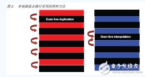
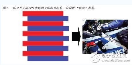
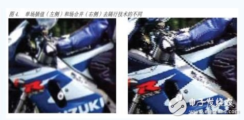
introduction The de-interlacing algorithm was developed to solve an old problem: interlaced video of analog TV must be converted to display on today's digital TV. Interlaced video is a 50/60 continuous field per second, with only half of the scan lines transmitted per field, which are displayed in each frame of the video. Interlaced video is a basic compression method for display technologies that previously used cathode ray tubes (CRTs). Today, deinterlacing is an important video processing feature that many systems need. Most video content uses an interlaced format, and almost all newer displays, such as LCDs or plasmas, require progressive video input. However, deinterlacing is inherently complex and no algorithm produces perfect progressive images. background In interlaced video, a frame of video is divided into two fields, one containing even rows of scan lines and one containing odd rows of scan lines. However, in order to be able to display any interlaced video on an LCD or plasma display, deinterlacing must be performed. All new displays are progressive, with each frame being compressed into a set of pixels (for example, 1920 x 1080). Figure 1 shows how the pixels in a frame form two fields. The pixel values ​​separated in time are recorded for each field. If you assume 30 frames per second (fps), or 60 fields per second, then field 0 is at time "t" and field 1 is at time "t + 1/60". Since the fields are recorded at slightly different time intervals, it is not possible to join the two fields together to produce a progressive frame for the motion video. Deinterlacing It is complicated because it is necessary to estimate and compensate for possible 1/60 moving images per second. Basic deinterlacing Basically, deinterlacing is the process of processing an interlaced frame stream and converting it into a progressive frame stream. Two basic deinterlacing methods are commonly referred to as "single field interpolation" and "occasional" methods. With "single field interpolation" deinterlacing, each field can be turned into a video frame, so the 29.97-fps interlaced NTSC clip video stream becomes a progressive frame of 59.94-fps. Since each field has only half of the scan line of the entire frame, interpolation processing must be performed to form the missing scan line. It can also be said that the single field interpolation deinterlacing technique doubles the scanning line spatially, and the scanning line of each field is doubled. The new line produced can be either a simple copy of the previous line (scan line copy) or an average of the preceding and succeeding lines (scan line interpolation), as shown in Figure 2. When the brightness of the image changes relatively smoothly, the result of the single-field interpolation deinterlacing technique is better, but since the technique reduces the vertical resolution, the image becomes softer. Deinterlacing and techniques involve merging two fields, which form a complete frame in a time-separated field, as shown in Figure 3. If the image has no motion part (for NTSC video) within 1/60 second of the two separate sessions, then the result is better. Sometimes, when a pair of interlaced fields comes from the original progressive frame, the algorithm will be very good. However, if there is a moving part, an artifact such as "sawtooth" will appear. Single-field interpolation and occasional de-interlacing can affect image quality, especially when the image has moving parts. Single-field interpolation softens the image, and occasionally produces a rough image, or a jagged artifact. Figure 4 compares the images generated by the single-field interpolation method and the images generated by the interlaced method. Advanced deinterlacing Obviously, the two methods described above can be used at the same time. First, whether there is a moving image between the frames before and after the video, thereby producing a better quality deinterlacing result. This method adopts the occasional method for the stationary region, and the moving portion adopts the single field interpolation method. Therefore, it is called "motion adaptive deinterlacing". More [ Details ]
Modular design of Optical Cable Cross Connection Cabinet(FDH,FOCC) provides the largest flexibility; satisfy the needs of the present and future development. The body using the stainless steel and surface using electrostatic spray so it has good corrosion resistance and anti-aging function, the wind protection class of the body achieves the IP66 level. The effect of defense dewing is excellent. The module tray can spin out of 90 degrees around the axis in the left front, and the bevel of the adapters within the module takes on 30 degrees. The clip-locked installation ensures the bending radius of the fiber directly and prevents the eyes from injury. Weld disk can spin out of 90 degrees, and then draw out, so it is convenient to construction, and also convenient to expansion and maintenance. Have doors in the front and back, have ample space for cabling, convenient to operation and maintenance. Have reliable device for fastness, peeling and grounding of the optical cables. Insulation resistance between high voltage protection earth and box20,000MΩ /500V (DC)
Communication Optical Cable Cross Connection Cabinet is interface equipment to contact trunk optical cable and wiring cable. It is compose of box, inside structure, optical fiber connector and some accessories. The function is to connect, store, dispatch and enlarge optical fiber. The material of box is cold-roll steel sheets, SMC fiber strengthen unsaturated polyester or stainless steel material. It has high resist destroy capacity, high strength, safety and stability. It has the device to bring optical cable, fix and protect. It has optical fiber termination device which could easy to splice, fix and maintain the optical cable fiber and optical cable fiber/optical fiber pigtail. At the same time, it has more space to store the surplus optical cable and fiber. Through the optical fiber connector, it could dispatch the fiber serial number of optical cable and change the transmission system route rapidly and expediently.
Optical Cable Cross Connection Cabinet Cross Connection Cabinet, Optical Cable Cross Connection Cabinet, FDH, FOCC NINGBO YULIANG TELECOM MUNICATIONS EQUIPMENT CO.,LTD. , https://www.yltelecom.com