The trend toward integrated active safety mechanisms in the automotive electronics industry has intensified, forcing automakers to integrate rollover prevention into traditional chassis control systems. For example, brake anti-lock braking systems and traction control systems have now been enhanced and integrated. Anti-rollover function. The National Highway Traffic Safety Administration (NHTSA) has further advanced this trend, mandated that all 2011 models and newer models must be equipped with rollover prevention controllers. This requirement is based on NHTSA's analysis of accident data for rollover collisions. For example, according to data provided by NHTSA's National Center for Statistics and Analysis, in 2001, a total of 10,138 people died from rollover crashes, accounting for 32% of the total number of deaths due to accidents that year. Implementing active safety mechanisms reduces the risk of vehicle rollover and reduces potential casualties. One way to reduce the risk of rollover is to implement Electronic Stability Control (ESC), which applies differential braking based on measured and predicted vehicle conditions. This article focuses on the development and automatic optimization of ESC for sport utility vehicles (SUVs) using model-based design. This article refers to the address: http:// Figure 1: Setting vehicle parameters using the CarSim user interface. Figure 2: Signals provided to the Signal Constraint module (left) and changes in rollover and slip rate signals during the optimization process (right side). The yellow area represents a range of signal values ​​that are not allowed. Figure 3: Visualized behavioral demonstration of an ESC with an ESC and an SUV without an ESC when performing a fishhook manipulation experiment at 50 mph. The blue SUV is equipped with an optimized ESC and the red SUV is not equipped with an ESC. Wall Wash Lights ,Led Wall Washer Light,Led Wall Washer,Wall Washers Guangzhou Cheng Wen Photoelectric Technology Co., Ltd. , https://www.cwledwall.com
Automotive and Controller Models In a model-based design, the core concept is an executable specification or model that describes the dynamic behavior of the system. You can take advantage of proven vehicle models (high-fidelity SUV models in this case) to significantly reduce development costs and time associated with controller design. The digital simulation of the model can be used to study the vehicle's response to different steering maneuver experiments, and such tests can be easily repeated under different parameters such as road surface, tire model and vehicle properties. In addition, models can be used in the development and validation of embedded control systems.
The car used in this article is a typical medium SUV. The vehicle model can be found in CarSim®, a ready-to-use commercial vehicle dynamics simulation tool. The performance of the vehicle model is verified against test data and is suitable for simulating the vehicle's response to severe roll motion. The vehicle model has two independent front suspensions and a solid rear axle for supporting sprung mass. The nonlinear mathematical model provides freedom for sprung mass, shaft, wheel, steering system and braking system. Vehicle models can be customized using different vehicle parameters as well as road and environmental conditions. 
Figure 1 shows the CarSim user interface and some of the physical vehicle parameters used to build the vehicle model. These parameters can be modified separately from the controller parameters to test the behavior of the controller under different vehicle conditions, such as one passenger, multiple passengers, and high center of gravity. The steering input for the vehicle model application used in this paper is in accordance with the NHTSA fishhook steering experiment, which is used to evaluate dynamic vehicle stability. This test is designed to simulate the actions the driver may take when avoiding obstacles that suddenly appear on the road. For digital simulation, we set the steering input for the SUV model, verifying that the vehicle will roll over without ESC.
Controller Development and Optimization The ESC implemented in this article avoids unsafe body roll and side-slip motion caused by driver's operation. It applies differential braking to the wheels to adjust the body roll and side slip ratio while minimizing vehicle speed reduction caused by electronic braking automatically applied by the controller. The ESC we implemented switches between the three control modes. The control mode is activated according to three possible incentives for the vehicle to enter the wheel slip state: loss of traction, excessive rollover, excessive skid. The mode switching logic controls a set of proportional-integral-derivative (PID) compensators that will adjust the brake pressure applied by the driver to the wheel based on the measured and predicted parameters. The controller design implemented in Simulink® has six PID gains that can be changed to optimize ESC performance.
In this model, we can look at wheel speed, brake pressure, body roll, side slip rate and slip rate. Some vehicle states are predicted by available sensor data, as in actual vehicle controllers, while others are predicted by mathematical relationships between measured and predicted parameters. The vehicle speed is predicted from the average wheel speed of the unbraking wheel. A low-pass filter is used to simulate the effect of vehicle inertia at the measured wheel speed, avoiding an indeterminate value in the vehicle speed measurement when applying brake pressure to four wheels.
If you do not use expensive sensors, the car body slip rate will be a parameter that is difficult to measure directly. The ESC we implement will predict the body slip rate from the measured slip rate. The body roll angle is predicted by a transfer function that relates the lateral acceleration to the body roll angle. This transfer function is effective when the body roll angle is within specified design limits. By ensuring that the optimization algorithm will impose a rigorous effect on the controller when the predicted body roll angle exceeds the design limit, we demonstrate that we do not need an estimation algorithm that accurately predicts the body roll angle beyond the design range. Therefore, we can significantly simplify the vehicle body roll angle prediction algorithm under normal vehicle operating conditions.
Once the controller structure is specified, the next task is to tune the controller gain to meet the design requirements. Without a model that can be experimented in a systematic way, engineers often rely on knowledge gained from past vehicle programs, or invest a lot of time to experiment with tuning the parameters of the PID compensator through road experiments. Model-based design frees this process from the hassle of hardware, but uses models to explore the design space. By combining these models with automated optimization-based methods, engineers can significantly reduce the need for cumbersome testing through prototyping or simulation to achieve optimal controller gain.
For this application, the optimization algorithm first sets the controller gain to zero. To find the optimal controller gain that guarantees the system is within design limits, a total of approximately 100 iterations are required with a computation time of approximately 4 minutes. Iterative trial and error rules require intensive manual testing, even if the test is completely repeatable, and the rollover during tuning does not cause any damage to the vehicle, and the same number of test cases will take more than 4 hours. . Digitally simulating a 10-second NHTSA fishhook manipulation experiment on a modern PC takes less than 3 seconds and can be repeated indefinitely without the overhead associated with road experiments.
In this model, we need to find the optimal controller gain for the PID compensator in the ESC to ensure that the vehicle's rollover angle, slip ratio and slip angle are within specific design limits while minimizing the difference Speed ​​loss caused by dynamic braking. Six tunable gains provide nearly unlimited controller gain combinations, and exhaustive testing is almost impossible. Simulink® Response OptimizationTM allows graphically setting system requirements, limiting body rollover and vehicle slip while minimizing energy loss from ESC braking. After specifying performance criteria, the optimization-based routine will automatically adjust the parameters so that the vehicle can perform fishhook manipulation experiments without rollover.
We provide the signal that needs to be limited to the Signal Constraint module and graphically set its design limits, as shown by the horizontal solid lines in Figure 2. We have chosen the following requirements (restrictions) to meet our design goals:
• The body roll angle is limited to +/-11.5 degrees.
• The vehicle slip angle is limited to +/-11.5 degrees.
• The maximum slip ratio is set to +/-37.25 degrees/second.
• The minimum speed at the end of the Fishhook control experiment is set to 10 mph.
• The time to end the simulation is set to 10 seconds.
To avoid early termination of the vehicle rollover simulation due to a set of incorrect controller gain values, a simulation time limit needs to be specified. 
Each signal limit defines the piecewise linear upper and lower limits of the signal. During the optimization process, the controller gain will be adjusted and the simulation will run repeatedly in the iterative loop until the simulated signal meets the specified boundary or the optimization routine cannot solve the problem. Figure 2 shows the changes in the rollover and slip rate signals during the iterative solution of the optimization algorithm. In solving such a feasibility problem, the optimization algorithm will calculate the maximum signed distance between the restricted signal and the linear boundaries of each segment. Normally, a negative value indicates that the corresponding limit has been met.
The optimization algorithm uses the signed distance between each boundary to update the controller parameters. In constructing optimization problems, the way the optimization algorithm is used is independent of the numerical solution of the state of the computing system. Gradient-based or non-gradient-based methods, such as genetic algorithms, can be used. In this example, given the switching characteristics of the controller and subsequent non-smooth behavior, a gradient-based solution is difficult to derive a global solution. Thus a pattern search algorithm is used. In practice, we recommend switching between multiple types of optimization methods to ensure that the optimization algorithm can find the global extremum and exclude the case of convergence to the local minimum of the cost function.
Controller Verification and Performance Verification Figure 3 graphically demonstrates the performance of the optimized ESC to avoid vehicle rollover. The red car is not equipped with a controller and a rollover occurs; the blue car is equipped with an optimized controller. Through such simulations, we can demonstrate the controller design that avoids SUV rollovers, which greatly reduces the number of road tunings and avoids relying entirely on actual vehicle testing. 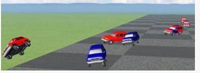
Next Steps and Conclusions In the design effort, the next steps typically involve moving the control algorithm from the Simulink model to the code implemented on the chassis controller. To perform design verification before the vehicle is put into production, an integrated rapid prototyping and semi-physical (HIL) simulation tool can be used to perform road testing of the code through a prototype car equipped with a measuring instrument. You can use the production code generation tool to implement the algorithm and get the code implemented on the prototype car, which minimizes errors in the conversion process and further accelerates the vehicle development process. In addition, using this model, engineers can test controllers in different vehicle configurations, support rapid modifications, and maximize the reuse of controller designs in a variety of vehicle programs.
This article highlights the application of model-based design in developing ESC algorithms that address rollover problems. It also demonstrates a way to automatically tune ESCs based on design requirements.