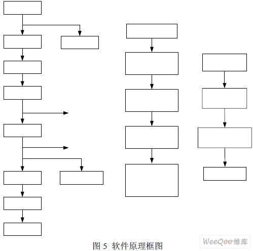
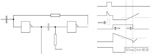
Design of High Precision Temperature Controller Based on HART Protocol 1 Introduction With the rapid development of control technology, computer technology, communication technology and the development needs of CIMS (Computer Integrated Manufacturing System), the field bus technology with field bus network as the overall mark has been produced, and it has developed rapidly, driving the control system structure and Automated instruments have advanced to the generation of fieldbus control systems and bus-based instruments. This article introduces micro-processing technology and HART protocol communication technology into the temperature controller, and implements a high-precision, multi-function programmable two-wire HART protocol high-precision temperature controller. 2 Overview of the hardware principle of the temperature controller The circuit block diagram of the high-precision temperature controller based on HART protocol, as shown in Figure 1. The two lines connected to the HART protocol temperature controller are both the power line and the 4-20mA output (control) signal line and the HART signal line. The current supplied to the HART protocol temperature controller is limited to less than 4mA (alarm 3.6mA) , The part above 4mA is the signal. AD421 produced by AD Company is used to realize A / D and V / I functions. AD421 is a low-power multifunction chip, which integrates 16-bit A / D, V / I and voltage adjustment circuits. DC / DC is a power isolator designed using the principle of switching power supply, through DC / DC to the temperature controller signal input and A / D circuit based on HART protocol. The use of low drive current photoelectric isolator for signal isolation, to achieve the HART protocol temperature controller sensor small signal input and output signals and external power supply isolation, while achieving the temperature controller's low current consumption requirements. The working principle of the circuit is: the temperature sensor signal is filtered and sent to the AD7714 for amplification and conversion into a corresponding digital signal. After being isolated by the optocoupler HP4731 and sent to the CPU, the CPU performs linearization and correction processing and sends it to the AD421 for conversion to the corresponding 4-20mA standard. Current output. In addition, the digital communication signal on the loop is filtered and sent to the demodulator HT2012, and the demodulated signal is sent to the CPU through the serial port. Then the CPU sends the corresponding response signal to HT2012 to modulate it into a HART digital signal. After shaping, it controls the V / I conversion circuit to convert it into a corresponding digital signal and superimposes it on the 4-20mA DC signal. 3 Detailed design of the hardware circuit 3.1 Signal isolation and determination of optocoupler peripheral parameters The information exchange between the A / D converter and the CPU is optocoupler isolation. 1) The determination of the external parameters of the optocoupler is shown in Figure 2. Taking the calculation of R18 and R20 as an example, since the minimum drive current of the optocoupler is IF = 40μA, it is solved according to equations (1) and (2). Considering the worst case and the margin, R18 = 62KΩ, and R17 = 62KΩ for the same reason. The calculations for R15, R16, R21, R22 are similar and will not be described here. 2) The pulse width expansion circuit is shown in Figure 3. Figure 3 Pulse width expansion circuit and waveform After the data update of AD7714 is completed, its DRDY line should send a trigger high pulse with a width of 203.5μs, and the minimum response pulse width of the optocoupler is 500μs, so the pulse width expansion circuit must be set. Principle analysis, when the original state is set, points a, c and d in the figure are logic low levels; b and e are high levels, when the VI pulse comes, point b jumps to 2VCC, and then discharges to VCC, c, d , E point unchanged. When the negative transition edge of VI comes, the b, c, d, e points are reversed, and then C21 begins to discharge. When the potential at point d drops to the inverter conversion voltage value, the inverter state transitions, and point e becomes high Level, and charge C13, when the potential at point b rises to the inverter conversion voltage value, the inverter state transitions, point C becomes low, and a steady-state pulse is drawn from point C. Since the DRDY high pulse width of AD7714 is 500 × tCLKIN = 203.5μs, T3 should be less than 203.5μs, T3 = -R14C13ln0.5 and R14 = 200KΩ to find C13 <1.5nf, T2 = -R14C13ln0.33 = 113μs T1 =- R13C21ln0.33 = TW-T2, because the minimum pulse width of the optocoupler is 500μs. Consider the margin to take TW = 2.3ms. R13 takes 200KΩ to get C21 = 0.00978μf, and C21 = 0.01μf. 3.2 Signal input circuit design The signal input part is connected with single-pair, double-pair, double-resistance, two-wire thermal resistance, three-wire thermal resistance, four-wire thermal resistance, high-frequency bypass feedthrough capacitor, constant current source, low-pass filter network (R1 -R6, C3-C8) and other components. The feed-through capacitor is used to attenuate the high-frequency signal connected to the signal line. Considering the insulation strength of the signal line to ground, a 100P / 500V feed-through capacitor is selected. The low-pass filter network adopts RC filtering, considering the input impedance requirements of AD7714, R selects 1.1K, and C selects 0.1μf. R9 and R10 are used for sensor disconnection detection, the resistance value is 22MΩ. The input circuit also considers the lead resistance compensation calculation when detecting the resistance signal. 3.3 Communication signal filter circuit The communication signal filter circuit is shown in Figure 4. The filter circuit consists of a high-pass and a low-pass filter. The HART communication signal contains the upper and lower half waves. In order not to cause signal distortion, the DC operating point is set at Vcc / 2. The second-order high-pass filter is composed of C33, C34, R24, R27 and D2C. If C33 = C34 = C and R24 = R27 = RZE, the transfer function is (3). According to the requirements of technical indicators, the temperature controller based on HART protocol should be intrinsically safe, so all large energy storage components in the circuit should be added with voltage limiting or current limiting protection components to meet the requirements of intrinsic safety indicators. In the aspect of reliability design, the derating design technology is adopted, so that the actual working stress of most components is ≤0.1. 4 Software implementation of temperature controller based on HART protocol The development of temperature controller software is based on the research of HART protocol data link layer and application layer, combined with the temperature controller's own functional requirements and the connection of hardware circuits. To realize the temperature controller, in addition to considering the hardware design, software design is another important aspect. According to the functional requirements and technical indicators of the temperature controller, the main contents of the software design are: a. According to the HART protocol specification, complete the slave device data link layer, application layer and inter-layer interface program to realize HART communication link connection, link arbitration, signal reception, identification, response and transmission. b. Consider signal acquisition compensation, linearization processing and output. c. Complete the interface program according to the device interface. d. Realize fault identification and alarm, local debugging and display. The working principle of the software is shown in Figure 5, which is mainly divided into three parts, one part is the collection and output of the signal; the other part is the arrival of the HART communication signal, entering the interrupt, identifying and responding to the communication signal, including the data link layer, application layer and layer Some programs such as the interface; the other part is to configure local parameters when a button is pressed. The author of this article innovation: The high-precision temperature controller based on HART protocol, compared with traditional field instruments or intelligent field instruments, has a leap in function, that is, the function of two-way digital communication is added, so that the temperature controller has many advantages in industrial processes The control system, the instrument management system and the network where these two systems coexist have a good application prospect. 20W Pd Charger,20Wpd Fast Charger,Ultrathin 20Wpd Fast Charger,20Pd Usb-C Phone Charger Guangdong Mingxin Power Technologies Co.,Ltd. , https://www.mxpowersupply.com


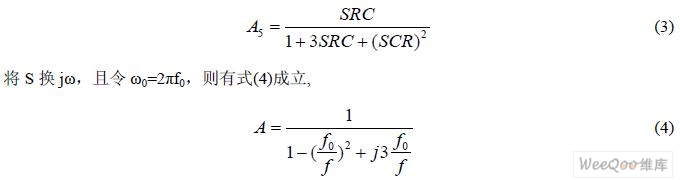
Taking (4) the denominator pattern is equal to v2, the cut-off frequency is 0.37 / 2Ï€RC. According to the characteristics of the HART signal, the high-pass cut-off frequency is generally 600 Hz. The first-order low-pass filter is composed of R22, R23, C30 and D2B. If C22 = R and C30 = C, the cut-off frequency is 1 / 2Ï€RC, and 2500Hz is generally used in HART communication.